Automatic sample clamping structure and gas permeation testing system
A clamping and automatic technology, applied in permeability/surface area analysis, measuring device, suspension and porous material analysis, etc., which can solve the problem that manual clamping sample force is difficult to control and unify, and the barrier/permeability detection error is large. , instability and other problems, to achieve the effect of improving stability and detection accuracy, improving test efficiency and accuracy, and uniform sealing degree
- Summary
- Abstract
- Description
- Claims
- Application Information
AI Technical Summary
Problems solved by technology
Method used
Image
Examples
Embodiment 1
[0065] Hereinafter, this embodiment will be described by taking the first test chamber and the second test chamber relative to each other up and down as an example:
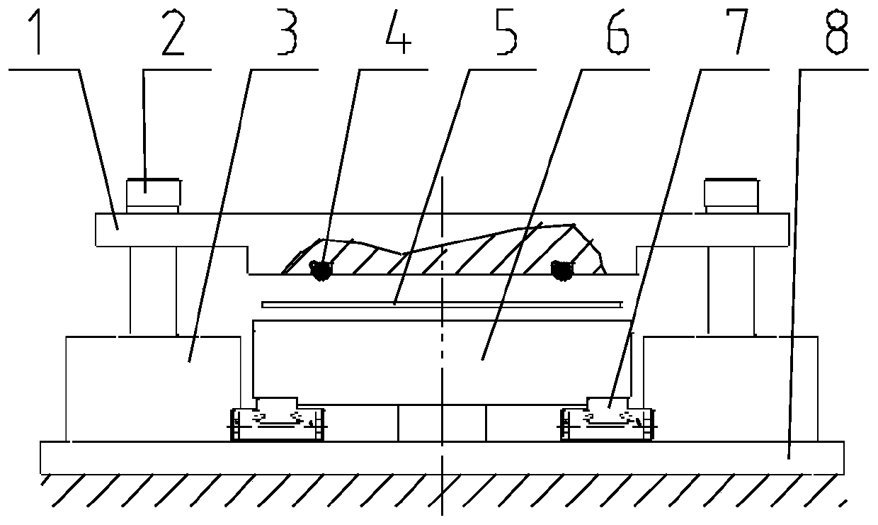
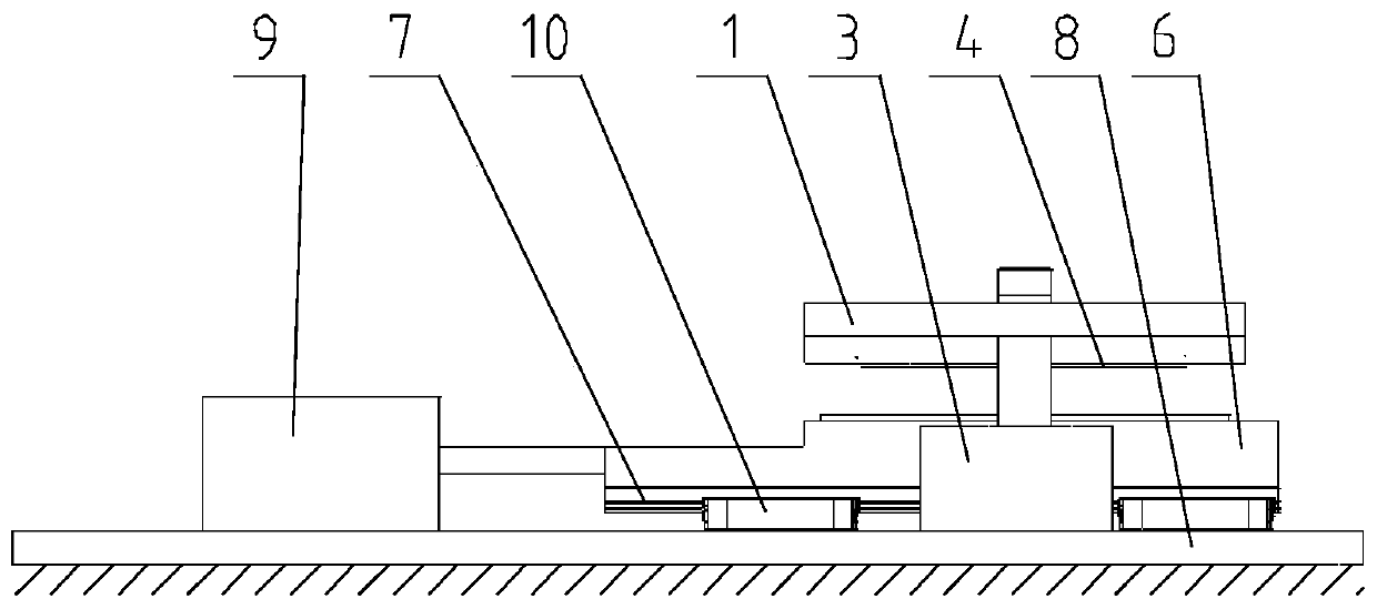
[0066] Such as figure 1 and figure 2 As shown, a sample automatic clamping structure of this embodiment includes:
[0067] The first test cavity 1 and the second test cavity 6; the sample 5 is arranged between the first test cavity 1 and the second test cavity 6; the first test cavity 1 and the second test cavity 6 are respectively arranged on the sample 5 above and below;
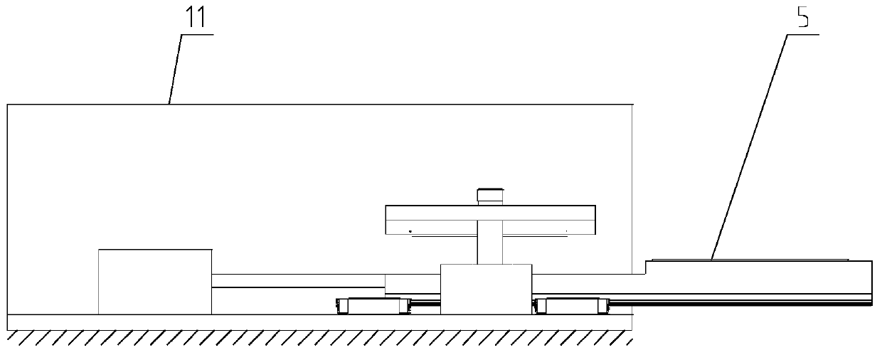
[0068] Before clamping the sample, the first driving device is used to drive the first test cavity to move upwards, and the second drive device is used to drive the second test cavity to move horizontally, so that the first test cavity and the second test cavity are separated and the second test cavity is separated. The second test chamber protrudes from the outside of the environmental chamber;
[0069] When the sample is placed in the ...
Embodiment 2
[0108] Such as Figure 4 and Figure 5 As shown, the difference from the first embodiment is that in the automatic sample clamping structure of this embodiment, the cylinder i3 is fixed on the second fixing plate 12 , and the cylinder ii9 is fixed on the first fixing plate 8 . Wherein, the first fixing plate 8 is arranged below the second testing chamber 6 , and the second fixing plate 12 is arranged above the first testing chamber 1 .
[0109] The opening and closing of the first test chamber and the second test chamber in this embodiment are driven by the driving device, the sample is well sealed, and the compression degree is consistent, and the purpose of stable test data and high detection accuracy is achieved; the test of this embodiment The sample automatic clamping structure realizes the automation of the entire clamping process and improves the efficiency of clamping the sample; the automatic sample clamping structure of this embodiment has a high degree of automation ...
Embodiment 3
[0111] A sample automatic clamping structure in this embodiment includes:
[0112] A first test chamber and a second test chamber, a sample is arranged between the first test chamber and the second test chamber; the first test chamber and the second test chamber are respectively arranged above and below the sample;
[0113] a first driving device, which is connected to the first test cavity;
[0114] a second driving device, which is connected to the second test cavity;
[0115] Before the sample is clamped, the second driving device is used to drive the second test cavity to move down a second preset distance, and the first drive device is used to drive the first test cavity to move in the horizontal direction, so that the first test cavity and the second test cavity The two test chambers are separated and the first test chamber protrudes outside the environmental chamber;
[0116] When the sample is adsorbed to the first test chamber, the first driving device is used to dr...
PUM
 Abstract
Description
Claims
Application Information
 - R&D Engineer
- R&D Manager
- IP Professional
- Industry Leading Data Capabilities
- Powerful AI technology
- Patent DNA Extraction
Browse by: Latest US Patents, China's latest patents, Technical Efficacy Thesaurus, Application Domain, Technology Topic, Popular Technical Reports.
© 2024 PatSnap. All rights reserved.Legal|Privacy policy|Modern Slavery Act Transparency Statement|Sitemap|About US| Contact US: help@patsnap.com


