Partially prefabricated section steel-concrete combined column based on side plates and application of partially prefabricated section steel-concrete combined column
A combined column and concrete technology, applied in the direction of columns, pillars, pier columns, etc., can solve the problems that the use of structures and mechanical performance cannot be effectively guaranteed, the requirements for on-site construction personnel and construction conditions are high, and the construction process is not effectively simplified. , to achieve the effect of ensuring normal use and carrying capacity, improving comprehensive mechanical performance, and enhancing restraint effect
- Summary
- Abstract
- Description
- Claims
- Application Information
AI Technical Summary
Problems solved by technology
Method used
Image
Examples
Embodiment 1
[0061] Example 1: A partially prefabricated steel-concrete composite column based on side panels
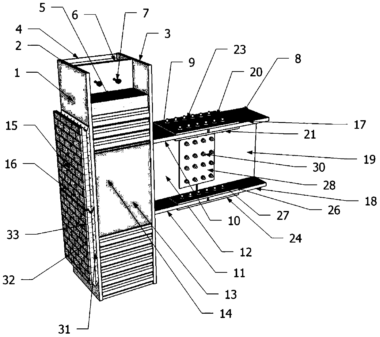
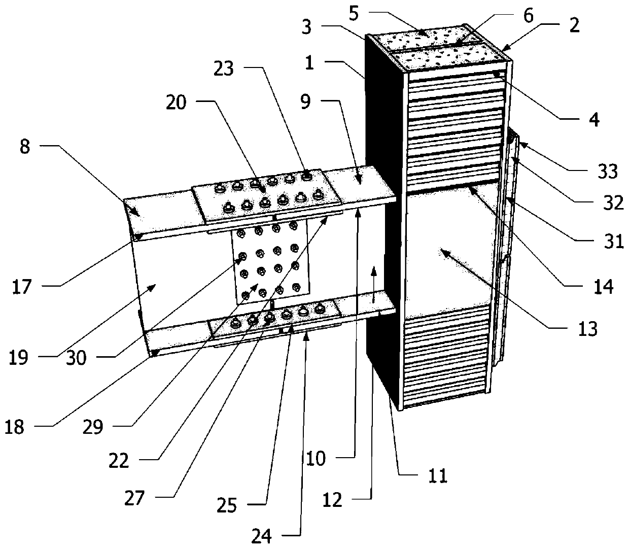
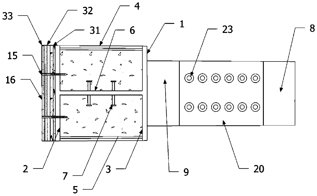
[0062] Such as Figure 1-3 , a partially prefabricated sectioned steel-concrete composite column based on a side plate comprises a first H-shaped steel 1, the two ends of which are respectively connected to the sides of the first upper flange plate 2 and the first lower flange plate 3 of the first H-shaped steel 1 The plate 4 is filled with the cast-in-place concrete 5 in the cavity formed by the first upper flange plate 2, the first lower flange plate 3 and the side plate 4 of the first H-shaped steel 1, and the cast-in-place concrete 5 is built in and respectively A number of studs 7 connected to both sides of the first web 6 of the first H-shaped steel 1; the side plate 4 is parallel to the first web 6 and one side of the side plate 4 is close to the cast-in-place concrete 5; One side is not in contact with the cast-in-place concrete 5 .
[0063] As a further preference, the...
Embodiment 2
[0078] Example 2: A construction method for partially prefabricated steel-concrete composite columns based on side slabs
[0079] Option A: Need to be connected with steel beams
[0080] Specific steps are as follows:
[0081] Weld the pegs 7 to the first web 6 of the first H-shaped steel 1 according to the designed distance, and fix the prefabricated plate 15 to the first upper flange plate 2 or the first lower flange of the first H-shaped steel 1 through the first bolts 16. On the flange plate 3, according to the quantity and position of the steel beams 8 to be connected, the second H-shaped steel 9 is welded to one of the first upper flange plate 2 and the first lower flange plate 3 that is not fixed with the prefabricated plate 15 On, the reinforced steel plate 14 is welded between the first upper flange plate 2 and the first lower flange plate 3 of the first H-shaped steel 1 located in the densified area 13, and the side plate 4 is welded to the first flange plate locate...
Embodiment 3
[0085] Example 3: A method for connecting partially prefabricated steel-concrete composite columns and steel beams based on side slabs
[0086] Specific steps are as follows:
[0087] The third upper flange plate 17, the third lower flange plate 18 and the third web 19 of the steel beam 8 are respectively connected with the second upper flange plate 10, the second lower flange plate 11 and the second H-shaped steel 9. The second web 12 is connected;
[0088] The third upper flange plate 17 is connected to the second upper flange plate 10 through the first flange splicing plate 20, the second flange splicing plate 21 and the third flange splicing plate 22; The plate 20 is close to the top of the third upper flange plate 17 and the second upper flange plate 10; the second flange splicing plate 21 and the third flange splicing plate 22 are close to the third upper flange plate 17 and the second Below the two upper flange plates 10; the second flange splicing plate 21 and the th...
PUM
 Abstract
Description
Claims
Application Information
 - R&D
- Intellectual Property
- Life Sciences
- Materials
- Tech Scout
- Unparalleled Data Quality
- Higher Quality Content
- 60% Fewer Hallucinations
Browse by: Latest US Patents, China's latest patents, Technical Efficacy Thesaurus, Application Domain, Technology Topic, Popular Technical Reports.
© 2025 PatSnap. All rights reserved.Legal|Privacy policy|Modern Slavery Act Transparency Statement|Sitemap|About US| Contact US: help@patsnap.com


