
Multi-angle pneumatic badminton serving machine

A badminton, multi-angle technology, which is applied in the field of multi-angle pneumatic badminton serving machines, can solve the problems of not having the function of autonomously planning and moving the ball, insufficient contact between the shuttlecock and the pneumatic nozzle, and insufficient positioning accuracy of the shuttlecock, achieving simple structure and reduced size , the effect of uniform force

Inactive Publication Date: 2019-05-24
CHONGQING UNIV OF ARTS & SCI
View PDF0 Cites 0 Cited by
  • Summary
  • Abstract
  • Description
  • Claims
  • Application Information

AI Technical Summary

Problems solved by technology

Most of the existing badminton serving machines are fixed-point serving machines, that is, after being placed at a certain serving location, they serve at different pitch angles. They do not have the function of autonomously planning and moving the serving, and they cannot fully train the players.
And most of the existing badminton serving machines are mechanical serving machines, relying on a pair of high-speed rotating rubber wheels to extrude the shuttlecock, or using the hitting mechanism to hit the shuttlecock, the mechanical serving will cause certain damage to the shuttlecock itself, affecting the shuttlecock. Although a few badminton serving machines use the air blowing method, there will be no clamping force on the shuttlecock itself before and during the blowing service, resulting in insufficient positioning accuracy of the shuttlecock in the launch tube and contact between the shuttlecock and the pneumatic nozzle. Insufficient and gaps, resulting in the waste of part of the blowing energy and the low accuracy of the ball control

Method used


Image

  • Multi-angle pneumatic badminton serving machine
  • Multi-angle pneumatic badminton serving machine
  • Multi-angle pneumatic badminton serving machine

Examples


Embodiment Construction

[0029] In order to make the object, technical solution and advantages of the present invention clearer, the present invention will be described in detail below in conjunction with the accompanying drawings and specific embodiments. It should be understood that the specific embodiments described here are only used to explain the present invention, not to limit the present invention.

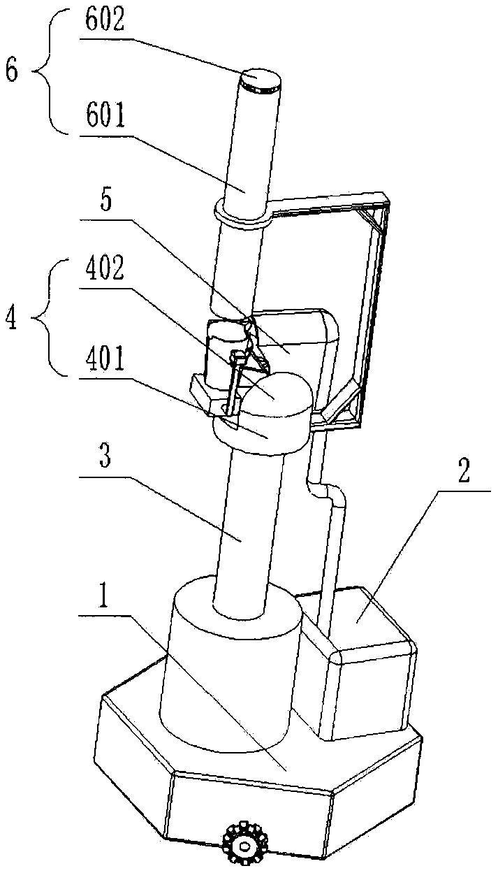
[0030] Such as figure 1 As shown, a multi-angle pneumatic badminton serving machine, a base 1, a control device 2, a lifting mechanism 3, a cloud platform 4, a serving mechanism 5 and a ball distributing mechanism 6, the bottom of the lifting mechanism 3 is fixed on the base 1 , The lifting mechanism 3 is a multi-stage telescopic cylinder, the cylinder is connected to the control device 2, and the control device 2 controls the lifting mechanism 3 to expand or contract step by step according to the demand. The top of lifting mechanism 3 is provided with cloud platform 4, and the structure of descr...


PUM


Abstract

The invention provides a multi-angle pneumatic badminton serving machine which comprises a base, a control device, a lifting mechanism, a ball taking and serving mechanism and a ball separating mechanism. The control device, the lifting mechanism, the ball taking and serving mechanism and the ball separating mechanism are arranged on the base, the ball separating mechanism is vertically arranged on the upper portion of the ball taking and serving mechanism and comprises a ball storage barrel and a stepping pressing-down device embedded in the ball storage barrel, the stepping pressing-down device is inserted in the ball storage barrel, the ball taking and serving mechanism comprises a ball taking and serving ejection rod and a prepositioning cone which is of a symmetric two-petal structure, an opening-closing device is arranged on each of two sides of the prepositioning cone and enables two petals of the prepositioning cone to be separated or fitted, and a linkage rod set is hinged between the prepositioning cone and the ball taking and serving ejection rod which can rotate in opposite directions through the linkage rod set. The multi-angle pneumatic badminton serving machine has the advantages that damage to badminton balls and energy friction loss can be reduced, and the machine is high in ball serving accuracy, little in pneumatic energy loss, supportive of remote control, compact in integral structure, convenient for carrying and space-saving.

Description

technical field [0001] The invention relates to the technical field of sports auxiliary equipment, and more specifically, relates to a multi-angle pneumatic badminton serving machine. Background technique [0002] Badminton is a sport that can be played both indoors and outdoors, and is loved by people of different ages. When performing badminton practice, the shuttlecock is usually fed to the position of the practitioner by hitting or throwing by a coach or a partner who is familiar with badminton. When the practitioner wants to practice a certain specific action, the badminton will be continuously sent to the practitioner with the same movement track, which will help the practitioner to quickly form muscle memory and master the specific action. Due to the way of manually hitting or throwing the ball, the height, position and parabola of the shuttlecock cannot be guaranteed to be the same every time, which is not conducive to improving the skill of the player or failing to...

Claims


Application Information

Patent Timeline
IPC IPC(8): A63B69/40A63B67/187
Inventor 赵立军吴忠建任文博陈爽陈卓徐鹏任屹
Owner CHONGQING UNIV OF ARTS & SCI
Learn More