System for deoiling an air-oil mixture for pressurising seals of a turbine engine

A turbine engine, pressurized air technology, applied in the direction of engine components, engine lubrication, engine function, etc., can solve problems such as reducing turbine engine maintenance operations, and achieve the effect of long mission duration

Inactive Publication Date: 2019-05-21
SAFRAN HELICOPTER ENGINES
View PDF7 Cites 0 Cited by
  • Summary
  • Abstract
  • Description
  • Claims
  • Application Information

AI Technical Summary

Problems solved by technology

it must also be able to reduce turbine engine maintenance operations

Method used


Image

  • System for deoiling an air-oil mixture for pressurising seals of a turbine engine
  • System for deoiling an air-oil mixture for pressurising seals of a turbine engine
  • System for deoiling an air-oil mixture for pressurising seals of a turbine engine

Examples


Embodiment Construction

[0040] In the drawings, for purposes of clarity and illustration, scale and dimensions have not been strictly adhered to.

[0041] For different elements of an oil removal system having the same function or of similar nature, the same reference numerals are used in the different figures.

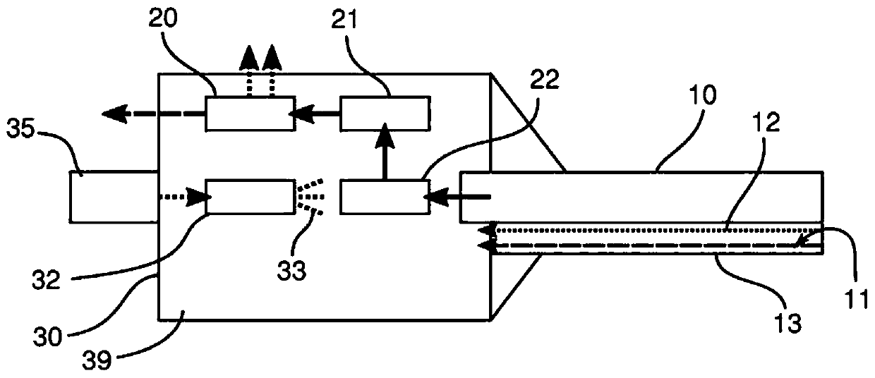
[0042] figure 1 Shown is a drive shaft 10 of a turbine engine equipped with an oil removal system according to the prior art. The drive shaft 10 is, for example, the row of gas generators and shafts of the free turbine of a turbine engine of a helicopter. Pressurized air, indicated by the solid arrow 11, is injected into the seal to ensure the sealing of the pressurized casing 13 of the turbine engine. Then, as the air 11 circulates within the pressurized housing 13, the air 11 is charged into the oil. exist figure 1In , the air and oil mixture circulating along the shaft 10 of the turbine engine is shown. Dashed line 11 represents air and dashed line 12 represents oil of the mixture. ...


PUM


Abstract

The invention relates to a system for de-oiling an air-oil pressurizing mixture (11, 12) for pressurized enclosures (13) of a turbine engine, said system comprising: at least one centrifugal degasser(20); at least one mechanical casing (30) of the turbine engine comprising a plurality of mechanical parts (21, 22), at least one of which is mechanically connected to a drive shaft of said degasser (20) so as to be able to rotate same, said casing (30) being configured to be able to contain an oil mist (39) for lubricating said mechanical parts (21, 22), characterized in that said de-oiling system also comprises means (40) for isolating said air-oil mixture (11, 12) from said oil mist (39) of said mechanical casing (30) so that said oil mist (39) of said mechanical casing (30) cannot enrich with oil said mixture to be separated by said degasser.

Description

technical field [0001] The present invention relates to oil removal systems for air-oil mixtures of pressurized seals or pressurized housings of turbine engines, such as carbon rings, brush seals, labyrinth seals, etc. . Background technique [0002] Turbine engines are complex systems implemented with many rotating units (turbine, compressor, etc.), which must be equipped with sealing means. These seals consist, for example, of pressurized air labyrinth seals, brush seals or carbon rings arranged in the vicinity of the rotary unit. For this, air is sucked in directly in the airflow of the turbine engine. This air then travels in the turbine engine through the different seals provided for this purpose and is expelled from the turbine engine in order to limit the pressure rise in other areas of the turbine engine, in particular reduction gears, accessory boxes, etc. However, the air that has traveled through the various regions of the turbine engine is filled with oil used...

Claims


Application Information

Patent Timeline
Patent Type & Authority Applications(China)
IPC IPC(8): F01D25/18F01M13/04
CPCF01D25/18F01M2013/0422F05D2260/609Y02T50/60F05D2260/98F16N7/32F16N39/002
Inventor 本杰明·弗勒瑞格让-皮埃尔·帕贾德
Owner SAFRAN HELICOPTER ENGINES
Why Eureka
Try Eureka