
Self-charging mouse based on permanent magnet vibration

A self-charging, permanent magnet technology, applied in the direction of current collectors, electromechanical devices, electric vehicles, etc., can solve the problems of energy loss, reduced convenience, limited charging range, etc., and achieve the effect of reducing waiting time and prolonging loss time

Inactive Publication Date: 2019-05-21
CHANGCHUN UNIV OF SCI & TECH
View PDF6 Cites 2 Cited by
  • Summary
  • Abstract
  • Description
  • Claims
  • Application Information

AI Technical Summary

Problems solved by technology

Cons: Requires a USB cable, limited charging range
Disadvantages: It needs to be used with a mouse pad, which increases the cost of use, and the efficiency of wireless charging is not high, and the energy loss is serious
Disadvantages: It needs to be used with a mouse pad, which increases the cost of use and reduces the convenience

Method used


Image

  • Self-charging mouse based on permanent magnet vibration
  • Self-charging mouse based on permanent magnet vibration

Examples


Embodiment 1

[0016] Embodiment 1. The self-charging mouse based on permanent magnet vibration includes a permanent magnet vibration charging module, an energy storage module and a control module. The permanent magnet vibration charging module is based on the principle of electromagnetic induction law, and an acrylic tube is placed inside the mouse. On the outside of the acrylic tube, 1000 turns of 0.08mm enameled wire are wound in a single layer to form a basic magnetic path, and then four permanent magnets are placed inside the acrylic tube, and then both sides are closed;

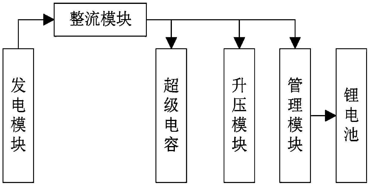
[0017] The energy storage module includes a rectifier module, a supercapacitor and a boost module, a management module and a lithium battery. The rectifier module uses a rectifier with a model MB6S single-chip microcomputer as the core to rectify the current. The boost module uses a TPS61222 single-chip microcomputer as the core. The voltage booster boosts the signal, and the management module uses a single-cell lithiu...

Embodiment 2

[0023] Embodiment 2, on the basis of Embodiment 1, it can be seen from the formula e(t)=n*Δφ / Δt that the magnetic flux Δφ needs to be calculated, assuming that the magnet is initially at the left end of the acrylic tube, and the initial value of the coil magnetic flux at the right end is 0, Δφ =φ2-φ1, the magnetic flux measured by the fluxmeter is about 0.004wb, and the average vibration time of one vibration can be found to be about 0.5s after many times of back-and-forth vibration, because the AC has a certain voltage drop after passing through the rectifier module, so it is set Assuming that e=7.5v, in practice φ1 cannot be completely 0, and there will still be a small amount of magnetic flux passing through, so the actual result n should be larger than the theoretical calculation result. Substituting the formula, it can be obtained that the coil is about 934 turns. In practice, according to 1000 turns winding.

[0024] In specific use of the present invention, the self-cha...


PUM


Abstract

The invention discloses a self-charging mouse based on permanent magnet vibration. The self-charging mouse comprises a permanent magnet vibration charging module, an energy storage module and a control module, wherein the permanent magnet vibration charging module is based on an electromagnetic induction law principle; an acrylic tube is placed in the mouse, and the outer side of the acrylic tubeis wound with 1000 turns of 0.08mm enameled wires to form a basic magnetic path, and then four permanent magnets are placed on the inner side of the acrylic tube, the two sides of the acrylic tube aresealed, and electric energy is generated by utilizing the permanent magnet vibration, so that the mechanical energy generated by mouse moving by a human can be converted into electric energy, and themouse can be charged, and therefore the loss time of the electric energy of the mouse is greatly prolonged; and the working state of the mouse can be quickly recovered within a short time under the condition that the mouse is thoroughly immersed; and the waiting time of a user during use is shortened.

Description

technical field [0001] The invention relates to the technical field of self-charging mouse, in particular to a self-charging mouse based on permanent magnet vibration. Background technique [0002] The current common charging methods are as follows: [0003] 1. USB wired charging: wired charging via USB cable. Advantages: The interface covers a wide area and the wires are easy to obtain. Cons: Requires a USB cable, limited charging range. [0004] 2. Wireless charging based on electromagnetic coils: place a transmitting coil in the mouse pad, place a receiving coil on the mouse, and charge with mutual induction. Advantages: To a certain extent, it gets rid of the shackles of the charging line. Disadvantages: It needs to be used with a mouse pad, which increases the cost of use, and the wireless charging efficiency is not high, and the energy loss is serious. [0005] 3. Charging with grid-shaped magnetic field distribution: alternately place magnets on the mouse pad, an...

Claims


Application Information

Patent Timeline
Patent Type & Authority Applications(China)
IPC IPC(8): H02J7/32H02J7/34H02K35/02G06F3/0354
CPCY02B40/00
Inventor 郝子强沈智利陈贺李光宇刘子铭唐涛
Owner CHANGCHUN UNIV OF SCI & TECH
Learn More