Liquid injection cup device

A liquid injection cup and liquid technology, which is applied to electrical components, circuits, battery pack components, etc., can solve the problems of harsh material requirements, wear and tear of rubber sealing rings, difficulties, etc. high cost effect

Pending Publication Date: 2019-05-21
速博达(深圳)自动化有限公司
View PDF6 Cites 0 Cited by
  • Summary
  • Abstract
  • Description
  • Claims
  • Application Information

AI Technical Summary

Problems solved by technology

[0003] However, due to the structural characteristics of the hard shell battery, the liquid injection port of the hard shell battery is relatively small. It is difficult for the electrolyte to enter the hard shell battery in a closed environment, and it is not easy to achieve. It is a production A crucial step for hard case batteries
[0004] The existing method of liquid injection for hard-shell batteries is to use a traditional lithium battery liquid injection machine for vacuum liquid injection. The key to realizing vacuum liquid injection lies in the sealing structure between the liquid injection needle and the vacuum cup, but the traditional liquid injection needle and the vacuum cup are sealed. The structure of the structure is complex, and the rubber sealing ring is required to act as a seal. During the cycle of liquid injection, vacuuming and positive pressure, the liquid injection needle will move up and down frequently, which is easy to cause wear and tear of the rubber sealing ring. Therefore, maintenance and replacement are required at most three months All the sealing rings, and the rubber fragments produced will flow into the battery, which will affect the performance of the battery. At the same time, because the sealing ring needs to be in contact with the electrolyte for a long time, the material of the sealing ring here is demanding, and it is required to be resistant to electrolyte corrosion and friction. , so the cost of money and manpower required to replace the sealing ring every time is very high

Method used


Image

  • Liquid injection cup device

Examples


Embodiment

[0031] This embodiment provides a liquid injection cup device, which is mainly used in lithium battery liquid injection machines, and can be used in combination with the vacuum pumping mechanism, positive pressure adding mechanism or liquid injection mechanism on the lithium battery liquid injection machine to respectively Realize the functions of vacuumizing the battery, adding positive pressure and injecting liquid.

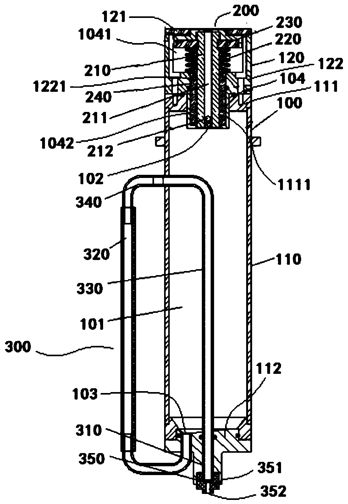
[0032] Please refer to figure 1 , the liquid injection cup device includes a vacuum cup 100 , a liquid guiding structure 200 and a liquid outlet structure 300 .

[0033] Wherein, the vacuum cup 100 has a cavity 101 for containing liquid, and an inlet 102 and an outlet 103 communicating with the cavity 101 . When filling the battery, the liquid is the electrolyte.

[0034] The liquid guiding structure 200 is sealed and arranged at the inlet 102, and the liquid guiding structure 200 is movable. On its moving path, there are at least a communication position thr...


PUM


Abstract

The invention discloses a liquid injection cup device comprising a vacuum cup, a liquid guide structure and a liquid draining structure; the liquid guide structure is hermetically arranged at an inlet; the vacuum cup is provided with a cavity for holding liquid and the inlet and an outlet communicated with the cavity; the liquid guide structure is movably arranged, a motion path of the liquid guide structure is at least provided with a communication position used for being communicated with the cavity via the inlet and a separation position used for exiting the inlet to be separated from the cavity; the liquid draining structure is hermetically arranged at the outlet, and used for draining the liquid in the cavity to a battery. The liquid injection cup device provided by the invention is good in sealing effect and high in reliability and liquid injection accuracy, and effectively solves the problem that the cost is high due to the fact that the rubber sealing ring needs to be changed periodically.

Description

technical field [0001] The invention relates to the technical field of lithium batteries, in particular to a liquid injection cup device applied to a lithium battery liquid injection machine. Background technique [0002] Lithium-ion batteries generally include lithium-ion hard-shell batteries and soft-packed aluminum-plastic film batteries. Because hard-shell batteries have the advantages of high energy, high battery voltage, wide operating temperature range, long storage life and small size, especially hard shell batteries Shell batteries are safer than soft-packed aluminum-plastic film batteries. Therefore, hard-shell batteries have been widely used in many fields such as military, power battery electric vehicles, and civilian use. [0003] However, due to the structural characteristics of the hard shell battery, the liquid injection port of the hard shell battery is relatively small. It is difficult for the electrolyte to enter the hard shell battery in a closed environm...

Claims


Application Information

Patent Timeline
Patent Type & Authority Applications(China)
IPC IPC(8): H01M2/36H01M50/60H01M50/636
CPCY02E60/10
Inventor 张建华何侦元王前蒋勇李国龙宋圳基
Owner 速博达(深圳)自动化有限公司
Why Eureka
Try Eureka