Eureka AIR delivers breakthrough ideas for toughest innovation challenges, trusted by R&D personnel around the world.

Piezoelectric excitation pulled silicon micro-resonant pressure sensor chip and preparation method thereof

A pressure sensor, piezoelectric excitation technology, applied in the manufacture/assembly of piezoelectric/electrostrictive devices, piezoelectric devices/electrostrictive devices, electric solid devices, etc., can solve temperature stability and packaging thermal stress Large impact, high requirements for electrode spacing control, complex optical system design, etc., to achieve strong anti-interference ability, improve detection accuracy, and improve sensitivity

Active Publication Date: 2019-05-21
XI AN JIAOTONG UNIV
View PDF3 Cites 19 Cited by
  • Summary
  • Abstract
  • Description
  • Claims
  • Application Information

AI Technical Summary

Problems solved by technology

Electrostatic excitation only requires two electrodes, which is easy to miniaturize, but the disadvantage is that the control of the electrode spacing is high; electromagnetic excitation requires a magnetic field, which is not easy to miniaturize; optical excitation requires the use of an optical path for excitation, and its optical system design is complex and miniaturization is difficult. Large; electrothermal excitation uses thermal stress caused by temperature difference to excite vibration, the disadvantage is that temperature stability and package thermal stress have a great influence

Method used


Image

  • Piezoelectric excitation pulled silicon micro-resonant pressure sensor chip and preparation method thereof
  • Piezoelectric excitation pulled silicon micro-resonant pressure sensor chip and preparation method thereof
  • Piezoelectric excitation pulled silicon micro-resonant pressure sensor chip and preparation method thereof

Examples


Embodiment Construction

[0047] The present invention will be described in detail below in conjunction with the accompanying drawings and specific embodiments.

[0048] In describing the present invention, it should be understood that the terms "center", "longitudinal", "transverse", "upper", "lower", "front", "rear", "left", "right", " The orientation or positional relationship indicated by "vertical", "horizontal", "top", "bottom", "inner", "outer", etc. are described based on the orientation or positional relationship shown in the drawings, and are only for convenience The description of the present invention and simplified description do not indicate or imply that the device or element referred to must have a specific orientation, or a specific orientation configuration and operation, and thus should not be construed as limiting the present invention.

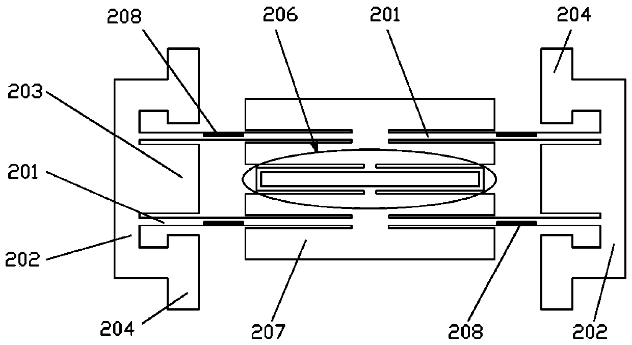
[0049] refer to figure 1 and figure 2 , the piezoelectric excitation and tension silicon microresonant pressure sensor chip includes a sealing gl...


PUM


Abstract

The invention provides a piezoelectric excitation pulled silicon micro-resonant pressure sensor chip and a preparation method thereof. The pressure sensor chip mainly comprises a sealed glass cover, aresonator layer, a pressure sensitive film layer, a stress isolation pad, a piezoelectric excitation element and a resistance vibration pick-up element. A composite structure of a pressure sensitivediaphragm and a resonator is adopted. For a second sensitive mode, the resonator layer comprises a resonant beam and a torsion beam. An extension part at one end of two adjacent resonant beams is connected to the same suspended torsion beam, and the other end is connected to a mass block. A coupling beam is arranged in the middle of the mass block. The resonator is connected to an anchor point through a connection point. A pressure guide hole is formed in the stress isolation pad, and the pressure is delivered to the rectangular pressure sensitive diaphragm under the guidance of the pressure guide hole to cause deformation. The deformation is amplified by the anchor point, and delivered to the resonator layer. Piezoelectric actuators and resistive vibration pick-up elements are respectively arranged on the outer surface of the resonant beam and the coupling beam. The piezoelectric actuators and the resistive vibration pick-up elements are connected with an external circuit through leads respectively.

Description

technical field [0001] The invention belongs to the field of micro-nano manufacturing and sensing, and in particular relates to a piezoelectric excitation and tension silicon micro-resonance pressure sensor chip and a preparation method thereof. Background technique [0002] The working mechanism of the silicon microresonant pressure sensor is to measure the pressure indirectly by measuring the change of the natural frequency of the resonator. It has the characteristics of high precision, good long-term stability, and low power consumption. It is widely used in aerospace, meteorological data acquisition, and navigation depth detection. , Industrial control and other fields. However, at present, 70% of the high-precision pressure sensors needed in China depend on imports, and procurement is difficult, which seriously affects the development of high-precision pressure measurement in my country. Therefore, it is very important to carry out research on high-precision resonant pr...

Claims


Application Information

Patent Timeline
Patent Type & Authority Applications(China)
IPC IPC(8): H01L27/20H01L41/09H01L41/25H10N39/00H10N30/03H10N30/20
Inventor 蒋维乐李雪娇赵立波韩香广方续东郭鑫卢德江王鸿雁吴永顺赵玉龙
Owner XI AN JIAOTONG UNIV
Why Eureka
Eureka Blog
Learn More