
Short-circuit detection device and method aiming at magnetic flux constraint type current-limiting switch

A current-limiting switch and short-circuit detection technology, which is applied in the direction of measuring devices, circuit breaker testing, and measuring electricity, can solve problems such as long time, slow current-limiting operation, and affecting current-limiting speed, so as to improve reliability, Effect of reduced fault detection time, fast and reliable design goals

Active Publication Date: 2019-05-21
HUAZHONG UNIV OF SCI & TECH +1
View PDF5 Cites 1 Cited by
  • Summary
  • Abstract
  • Description
  • Claims
  • Application Information

AI Technical Summary

Problems solved by technology

[0005] Aiming at the defects of the prior art, the purpose of the present invention is to solve the existing method for detecting short-circuit faults of lines to judge whether a short-circuit fault has occurred in the line according to the magnitude of the line current, and is affected by the line impedance and the initial state of the short circuit, resulting in the determination of the line fault. It takes a long time for the threshold current of the fault to occur, which causes the current limiting operation to be sluggish and affects the technical problems of the current limiting speed

Method used


Image

  • Short-circuit detection device and method aiming at magnetic flux constraint type current-limiting switch
  • Short-circuit detection device and method aiming at magnetic flux constraint type current-limiting switch
  • Short-circuit detection device and method aiming at magnetic flux constraint type current-limiting switch

Examples


Embodiment Construction

[0047] In order to make the object, technical solution and advantages of the present invention more clear, the present invention will be further described in detail below in conjunction with the accompanying drawings and embodiments. It should be understood that the specific embodiments described here are only used to explain the present invention, not to limit the present invention. In addition, the technical features involved in the various embodiments of the present invention described below can be combined with each other as long as they do not constitute a conflict with each other.

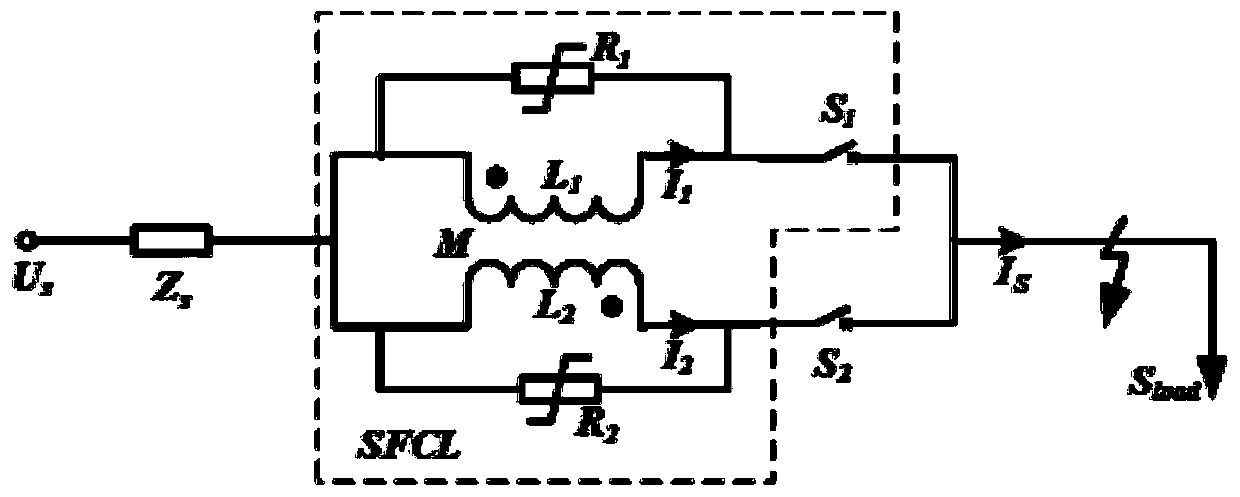
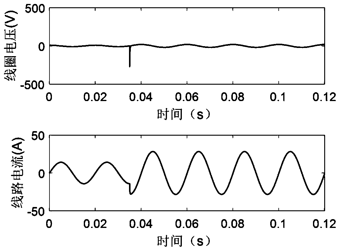
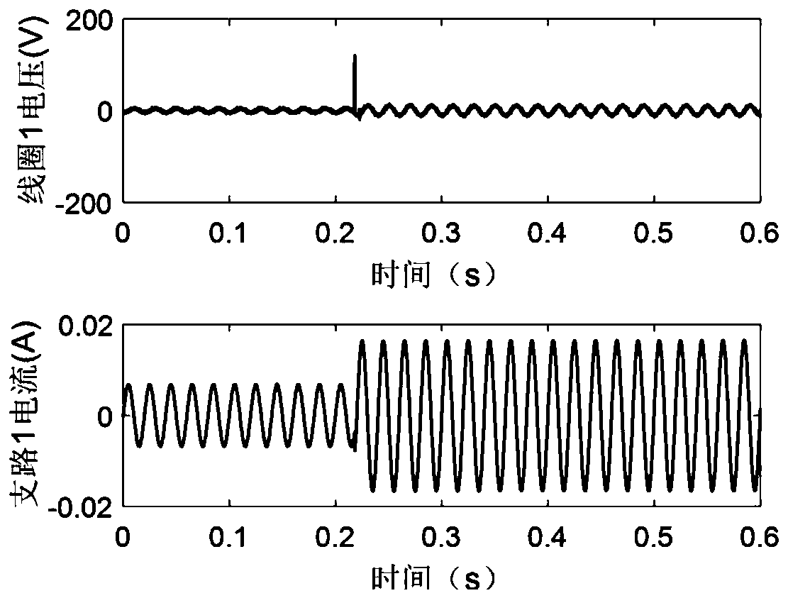
[0048]In order to start the current limiter in time after a short-circuit fault occurs, it is necessary to ensure that the short-circuit detection platform quickly detects the short-circuit fault. The present invention designs and develops a novel short-circuit detection platform according to the working characteristics of the flux-constrained current-limiting switch. The main detection sche...


PUM


Abstract

The invention discloses a short-circuit detection device and method aiming at a magnetic flux constraint type current-limiting switch. The short-circuit detection device comprises a voltage detectioncircuit and a current detection circuit, wherein when a short-circuit fault occurs in the circuit, induced voltages generated at the two ends of an inductance coil are suddenly changed; the voltage detection circuit is connected in parallel with two ends of the inductance coil and is used for detecting voltages at two ends of the inductance coil; the voltage detection circuit carries out voltage stabilization and voltage reduction processing on the detected voltages at the two ends of the inductance coil, judges whether the voltage value after voltage stabilization and voltage reduction processing exceeds a preset voltage threshold value or not, generates a short-circuit alarm signal if the voltage value exceeds the preset voltage threshold value, and starts the magnetic flux constraint type current limiting switch to carry out current limiting; the current detection circuit is used for detecting the current of a circuit where the magnetic flux constraint type current-limiting switch is located, when the current exceeds a preset current threshold value, it is judged that the circuit generates a short-circuit fault, and the magnetic flux constraint type current-limiting switch is started for current limiting. The short-circuit fault can be rapidly and effectively detected.

Description

technical field [0001] The invention relates to the application field of electric power technology, and more specifically, relates to a short-circuit detection device and method for a flux-constrained current-limiting switch. Background technique [0002] The protection technology of my country's power system has experienced the development process from transistor relay protection in the last century to integrated circuit protection in the 1990s, and then to computer relay protection in the 1990s. However, due to the rapid development of the power system, new requirements are constantly put forward for its protection technology, and the existing protection devices show their shortcomings. [0003] The short-circuit fault in the power system is one of the most serious faults in the system. The short-circuit current of the system caused by the short-circuit fault can reach hundreds of thousand amperes. If no timely measures are taken for the fault line, it will directly lead t...

Claims


Application Information

Patent Timeline
IPC IPC(8): G01R31/327G01R31/02
Inventor 朱凯任丽唐跃进石晶徐颖李敬东
Owner HUAZHONG UNIV OF SCI & TECH
Learn More