An automatic milling machine

A material machine and automatic technology, applied in the field of notebook computer manufacturing, can solve problems such as unbalanced force on the shell

Active Publication Date: 2021-05-18
重庆宇海精密制造股份有限公司
View PDF9 Cites 0 Cited by
  • Summary
  • Abstract
  • Description
  • Claims
  • Application Information

AI Technical Summary

Problems solved by technology

[0005] The purpose of the present invention is to provide an automatic milling machine to avoid the problem of unbalanced force on the shell when the shell is picked and placed due to the fault of the suction cup

Method used


Image

  • An automatic milling machine
  • An automatic milling machine
  • An automatic milling machine

Examples


Embodiment Construction

[0021] The preferred embodiments of the present invention will be described in detail below with reference to the accompanying drawings.

[0022] The reference signs in the accompanying drawings of the specification include:

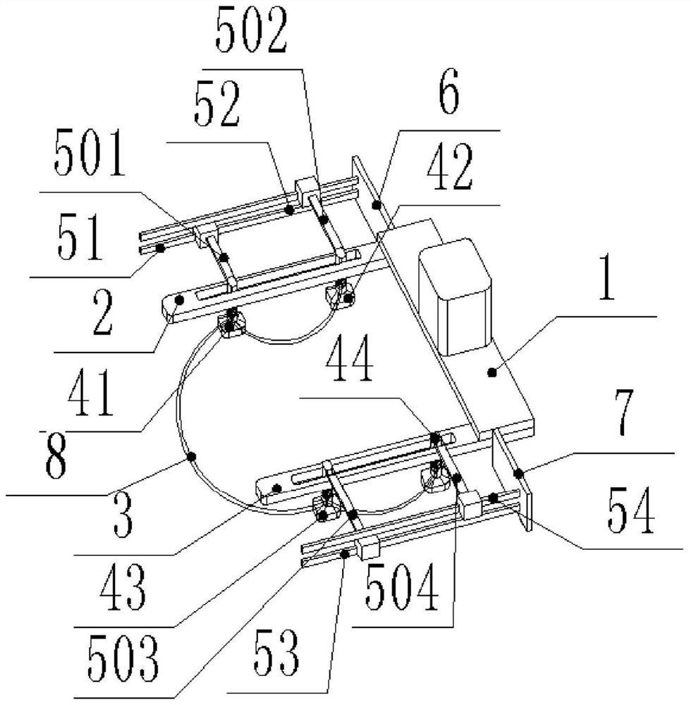
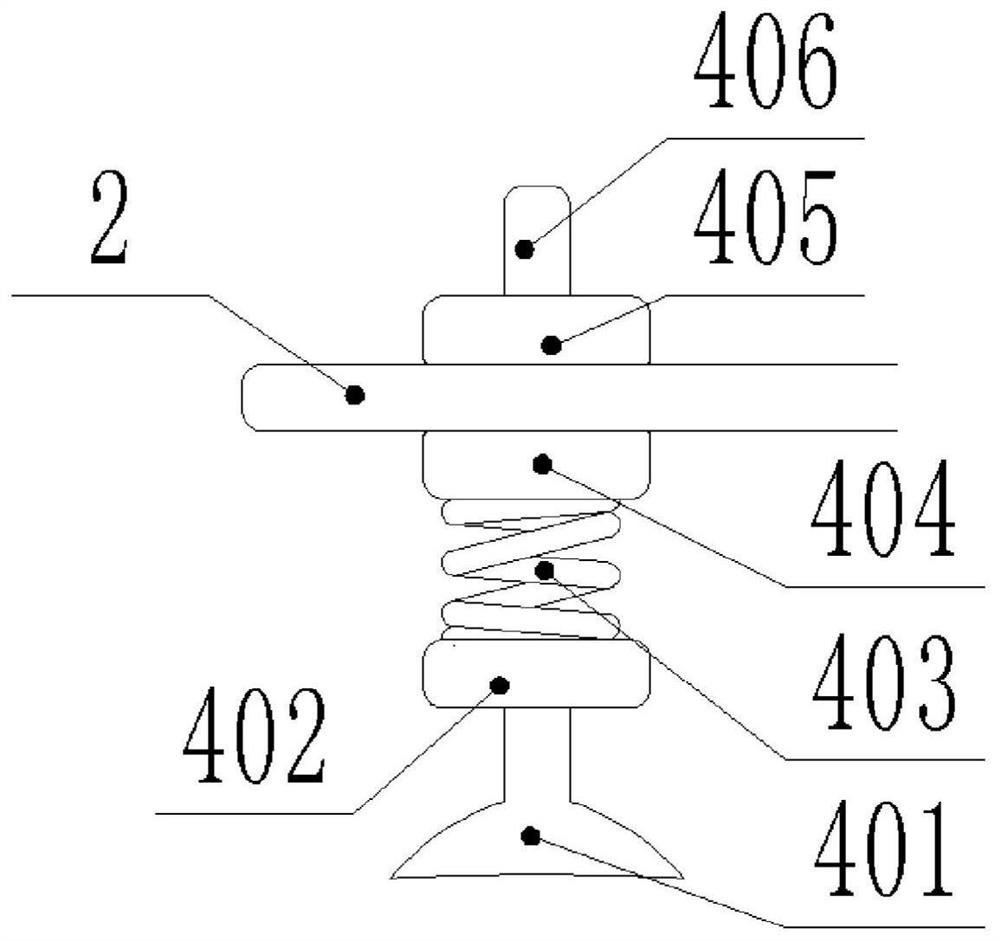
[0023] Fixed plate 1, first suction cup mounting plate 2, second suction cup mounting plate 3, suction nozzle 401, first connecting block 402, elastic element 403, second connecting block 404, third connecting block 405, connecting column 406, first Suction cup 41, the second suction cup 42, the 3rd suction cup 43, the 4th suction cup 44, the first linear motor 51, the first connecting rod 501, the second linear motor 52, the second connecting rod 502, the 3rd linear motor 53, the 3rd linear motor Three connecting rods 503, the fourth linear motor 54, the fourth connecting rod 504, the first motor mounting plate 6, the second motor mounting plate 7, the gas pipe 8, the first parallel plate B1, the second parallel plate B2, the insulating spring B3, Powe...


PUM


Abstract

The invention relates to the field of notebook computer manufacturing, in particular to an automatic milling machine, which includes a table for placing the casing, a milling cutter device for milling waste materials, a control unit, and a suction cup device. The suction cup device includes a suction cup, a mounting plate for installing the suction cup, The power device controlled by the control unit and the vacuum device that provides negative pressure for the suction cup have a through groove on the mounting plate, and the suction cup slides and fits with the mounting plate through the through groove. Movement in the through groove of the plate. The invention can avoid the problem of unbalanced force on the shell when the shell is picked and placed due to the failure of the suction cup.

Description

technical field [0001] The invention belongs to the field of notebook computer manufacturing, and in particular relates to an automatic milling machine. Background technique [0002] After the laptop casing is produced, the casing taken out from the injection mold will have splinters, so when the casing is taken out of the mold, the first thing to do is to remove the flakes. In the prior art, the milling method for the material head of the notebook computer casing is to place the product on an automatic milling machine of the prior art after the product is taken out from the mold for milling. [0003] For example, the Chinese patent whose publication number is CN105773931B discloses a milling material structure, which includes: a bracket; a feed slide, whose activity is located in the support, and a positioning fixture for placing products to be processed is provided on the feed slide; a pressing cylinder , which is fixed on the top of the feeding slide; the pressing plate,...

Claims


Application Information

Patent Timeline
Patent Type & Authority Patents(China)
IPC IPC(8): B29C45/42B29C45/43B29C45/38B29C45/76
Inventor 张大斌袁卫顺
Owner 重庆宇海精密制造股份有限公司
Why Eureka
Try Eureka