Section bar connector, section bar and section bar connecting structure

A technology for connecting structures and connectors, applied in the direction of structural elements, elongated structural members for load-bearing, building components, etc., can solve the problem of unbalanced force on connectors, poor waterproof performance, and wet and slippery ground outside the bathroom. and other problems, to achieve the effect of strengthening the bearing capacity, preventing the force unbalance, and increasing the force performance.

Active Publication Date: 2012-05-23
安徽克琳黛尔智能家居有限公司
View PDF1 Cites 0 Cited by
  • Summary
  • Abstract
  • Description
  • Claims
  • Application Information

AI Technical Summary

Problems solved by technology

The connectors and profiles adopting this structure, because the connection between the first body 2 and the second body 3 only depends on the mating groove and the mating protrusion, which is a monorail mating connection, and the connection part is not stable, causing the connector The unbalanced force makes the connecting parts vulnerable
Moreover, with this connection structure, the connection between the first body 2 and the first profile 5 is not strong enough, because it is only connected to the corresponding first profile 5 through the convex strip 23 on the end surface of the first body.
In addition, with this connection structure, after the connectors and their profiles are connected, the mating grooves and mating bumps of the first body 2 and the second body 3 are exposed outside the profiles, not only the appearance is not beautiful, but also the connection position The waterproof performance of the shower room is very poor, which will cause water to leak out of the shower room through the gaps in the connecting parts, causing the floor outside the shower room to be slippery

Method used


Image

  • Section bar connector, section bar and section bar connecting structure
  • Section bar connector, section bar and section bar connecting structure
  • Section bar connector, section bar and section bar connecting structure

Examples


Embodiment Construction

[0067] Below in conjunction with accompanying drawing and embodiment the present invention will be further described:

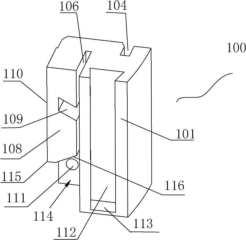
[0068] Such as Figure 1-12 As shown, the profile of the embodiment of the present invention includes a first profile and a second profile, and the first profile and the second profile are connected by a profile connector; the profile connector of the embodiment of the present invention consists of a connector main body 100, a connector main body two 200 and a locking part composed of three parts, wherein the locking part is a locking part that prevents the main body of the connector from being separated from the main body of the second connecting part; the first profile and the second profile are provided with parts corresponding to the structure of the profile connector.

[0069] Such as figure 1 As shown, a first chute 112 with a closed end and a sliding platform 110 arranged in parallel with the first chute are arranged on the front of the connector main...


PUM


Abstract

In order to overcome the defects of beauty and stress performance of the traditional section bar connecting structure, the invention relates to a section bar connecting structure as well as a section bar constituting the section bar connecting structure and a section bar connector matched with the section bar. The section bar connector comprises a connector main body (1), a connector main body (2) and a locking part preventing the connector from separating, the section bar comprises a first section bar matched with the connector main body (1) and a second section bar matched with the connector main body (2), a first chute and a slipway which are arranged on the connector main body (1) are respectively matched with a second U-shaped opening and a first U-shaped opening which are arranged on the first section bar, the connector main body (1) can be wrapped by the first section bar, an embedded protrusion arranged on the connector main body (2) is matched with an embedded cavity of the second section bar and embedded in the embedded cavity of the second section bar, the connector main body (2) is also provided with a first sliding rail matched with the first chute and a second sliding rail matched with the slipway, and the connector main body (1) and the connector main body (2) are locked and connected through the locking part.

Description

technical field [0001] The invention relates to a connecting piece for connecting profiles, the connected profiles and the connecting structure of the profiles, in particular to a quick assembly connecting piece for connecting the profiles used in the shower room, the connected profiles and the connecting structure of the profiles. Background technique [0002] In the shower room industry, the frame of the room body is mostly composed of two upper and lower beams and two side columns. There are three ways to assemble beams and columns: [0003] The first way is that there are connecting holes for screw fastening on the beam, and the hole diameter of the hole through which the screw passes through the column is larger than the nominal diameter of the screw and smaller than the screw head, and the screw passes through the column and enters the connecting hole in the beam to connect and fix. [0004] The second is to first install a fixed connector protruding from the column o...

Claims


Application Information

Patent Timeline
Patent Type & Authority Patents(China)
IPC IPC(8): E04H1/12E04C3/00E04B1/58A47K3/28
CPCE06B3/9642
Inventor 蔡建农
Owner 安徽克琳黛尔智能家居有限公司
Why Eureka
Try Eureka