
Self-balancing drilling and pulling-out mechanism with real-time bit pressure monitoring function

A self-balancing, real-time monitoring technology, applied in percussion drilling, rotary drilling, rotary drilling rigs, etc., can solve problems such as increased cost, large cumulative error, complex overall structure, etc., to avoid unbalanced force , avoiding the distortion of drilling pressure and improving the pull-out force

Active Publication Date: 2016-12-07
XIAN RES INST OF CHINA COAL TECH& ENG GROUP CORP
View PDF8 Cites 0 Cited by
  • Summary
  • Abstract
  • Description
  • Claims
  • Application Information

AI Technical Summary

Problems solved by technology

To further increase the pull-out force of the drilling rig, either increase the number of steel wire ropes or increase the cross-sectional area of ​​the steel wire ropes, which will lead to a complex overall structure of the drilling rig and an increase in cost. In addition, each steel wire rope is affected by elastic deformation and assembly errors. It is difficult to precisely control the length. The more the wire ropes are, the greater the cumulative error will be, which seriously restricts the further improvement of the drilling rig capacity.

Method used


Image

  • Self-balancing drilling and pulling-out mechanism with real-time bit pressure monitoring function
  • Self-balancing drilling and pulling-out mechanism with real-time bit pressure monitoring function
  • Self-balancing drilling and pulling-out mechanism with real-time bit pressure monitoring function

Examples


Embodiment Construction

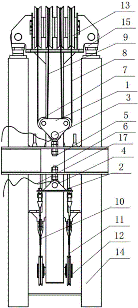
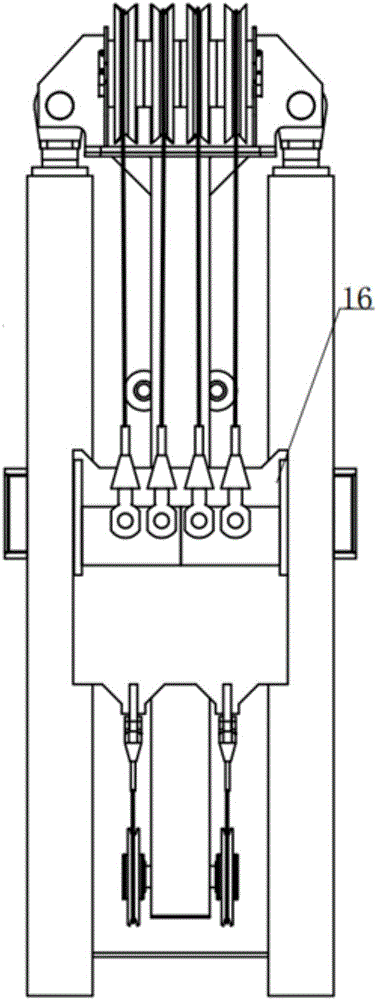
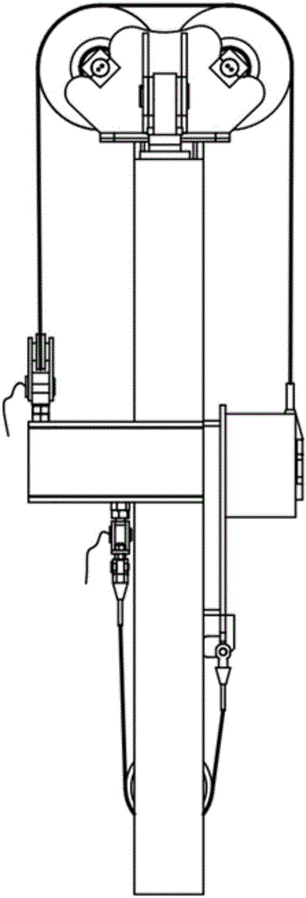
[0027] see Figure 1 to Figure 4 , shows the self-balancing drilling and pulling mechanism of the present invention with the function of real-time monitoring of the weight on bit.

[0028] The self-balancing drilling and pulling mechanism with the function of real-time monitoring of drilling pressure includes a primary fixed fuselage 14, a secondary oil cylinder feeding fuselage 15 and a power head support plate 16, and the primary fixed fuselage 14 is passed through a bolt It is installed on the drilling rig or the drilling rig frame in a fixed way, and then fixed. The feed body 15 of the secondary oil cylinder is telescopically arranged in the primary fixed body 14 through the oil cylinder, so that it can be stretched through the expansion and contraction of the oil cylinder. Drive the secondary oil cylinder to feed the fuselage 15 to move up and down relative to the primary fixed fuselage 14. The power head support plate 16 is located on the front side of the primary fixed ...


PUM


Abstract

A self-balancing drilling and pulling-out mechanism with a real-time bit pressure monitoring function comprises a first-stage fixed machine body, a second-stage oil cylinder feeding machine body and a power head supporting plate. The second-stage oil cylinder feeding machine body is arranged on the first-stage fixed machine body through an oil cylinder in a telescopic mode. The second-stage oil cylinder feeding machine body comprises a machine body part located between hollow square steel on the two sides. The upper end of the machine body part is connected to the free end of an oil cylinder telescopic rod in the first-stage fixed machine body through a cross beam. The power head supporting plate is located on the front side of the first-stage fixed machine body, and is connected to the first-stage fixed machine body after an upper self-balancing mechanism and a lower self-balancing mechanism wind around the upper end and the lower end of the second-stage oil cylinder feeding machine body correspondingly. Vertical motion of the power head supporting plate is achieved through vertical movement of the second-stage oil cylinder feeding machine body. Due to the facts that the self-balancing drilling and pulling-out mechanism is simple in structure, convenient to operate and capable of improving the pulling-out force and conducting real-time monitoring, the self-balancing drilling and pulling-out mechanism has practicability and applicability.

Description

technical field [0001] The invention relates to the technical field of drilling equipment, in particular to a self-balancing drilling and pulling mechanism with the function of real-time monitoring of drilling pressure. Background technique [0002] During the drilling construction process, the drilling rig mainly has two working conditions: drilling and pulling out. [0003] During the drilling and pulling out process, the drilling pressure of the drilling rig is one of the most important drilling process parameters. During the drilling and pulling out process, the drilling pressure of the drilling rig has a great influence on the drilling construction effect, drilling efficiency and drilling quality. Real-time and accurate monitoring of WOB is required during drilling and pulling out. At present, the drilling pressure of the full hydraulic drilling rig is not directly measured, but is generally calculated indirectly by measuring the pressure of the two oil ports of the do...

Claims


Application Information

Patent Timeline
IPC IPC(8): E21B44/00E21B44/02E21B19/084E21B3/02
CPCE21B3/02E21B19/084E21B44/00E21B44/02
Inventor 张阳常江华田宏亮凡东祁玉宁王贺剑刘祺邹祖杰鲁飞飞王瑞泽
Owner XIAN RES INST OF CHINA COAL TECH& ENG GROUP CORP
Learn More