
Numerical control detonator dissection machine tool and dissection method thereof

A detonator and machine tool technology, which is applied in the numerical control detonator anatomy machine tool and its anatomy field, can solve the problems such as the inability to realize the automatic positioning of the cutter head movement trajectory control, and achieve the effect of preventing damage and simple and convenient operation

Pending Publication Date: 2019-05-21
CHINA COAL TECH & ENG GRP HUAIBEIBLASTING TECHN RES INST
View PDF0 Cites 1 Cited by
  • Summary
  • Abstract
  • Description
  • Claims
  • Application Information

AI Technical Summary

Benefits of technology

This technology allows for precise control over both axes (X-axis) and Y-axis movements of an electric saw blade used with explosives or other dangerous materials. It uses two motors - one controlling its motion while another adjusts it based upon certain criteria like distance from the fixed part being exploded. By doing this, there're fewer steps needed than traditional methods involving moving parts around them. Additionally, when the blades break down they don’t harm anyone else who may come into contact with their body. Overall, these technical features improve efficiency and security measures for machinery tools such as sabers.

Problems solved by technology

This patented describes different types of industrial detonsector systems for use during excavations or demolitions operations. These include electrical and hydraulic type detronizers, which require manual operation by operators who must move their tools around frequently when they exit from workplaces. Additionally, there exist other specialized instruments called NC/Electric Detor Anatomic Machine Tool ("CDA"). They also involve moving parts like electronics inside them while still being able to perform certain functions effectively without requiring human labor. However these conventional methods lack flexibility due to limitations caused by factors including poor quality controllers, limited battery life time, and unreliable communication protocol between sensors themselves. Therefore, new solutions are needed to improve upon this problem.

Method used


Image

  • Numerical control detonator dissection machine tool and dissection method thereof
  • Numerical control detonator dissection machine tool and dissection method thereof
  • Numerical control detonator dissection machine tool and dissection method thereof

Examples


Embodiment Construction

[0029] The following will clearly and completely describe the technical solutions in the embodiments of the present invention with reference to the accompanying drawings in the embodiments of the present invention. Obviously, the described embodiments are only some, not all, embodiments of the present invention.

[0030] Examples of the described embodiments are shown in the drawings, wherein like or similar reference numerals designate like or similar elements or elements having the same or similar functions throughout. The embodiments described below by referring to the figures are exemplary and are intended to explain the present invention and should not be construed as limiting the present invention.

[0031] In describing the present invention, it should be understood that the terms "center", "longitudinal", "transverse", "length", "width", "thickness", "upper", "lower", "front", " Back", "Left", "Right", "Vertical", "Horizontal", "Top", "Bottom", "Inner", "Outer", "Clock...


PUM


Abstract

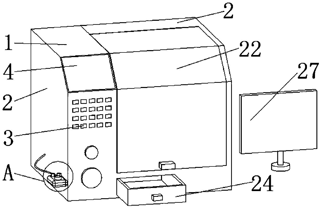
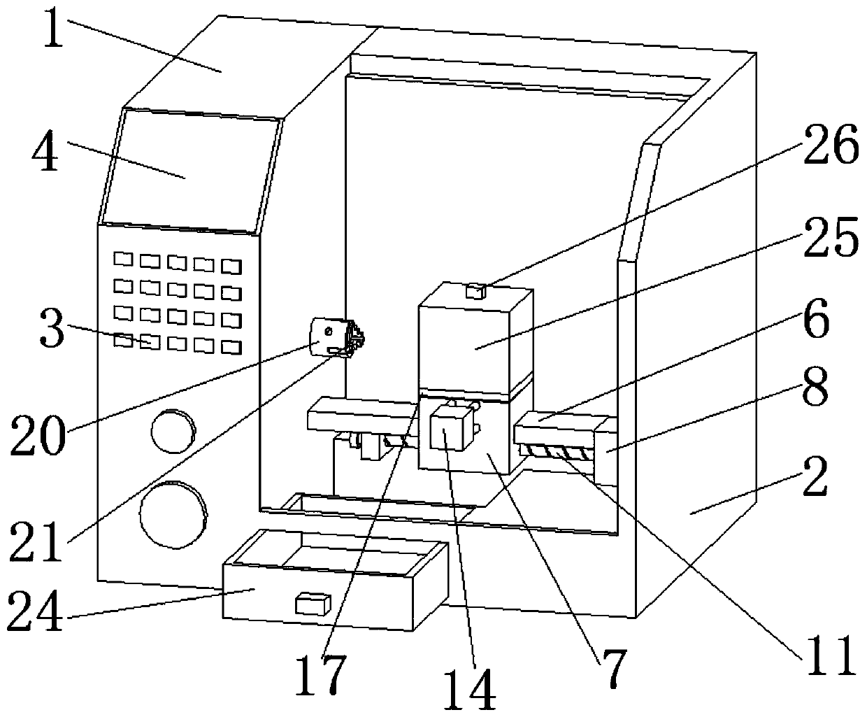
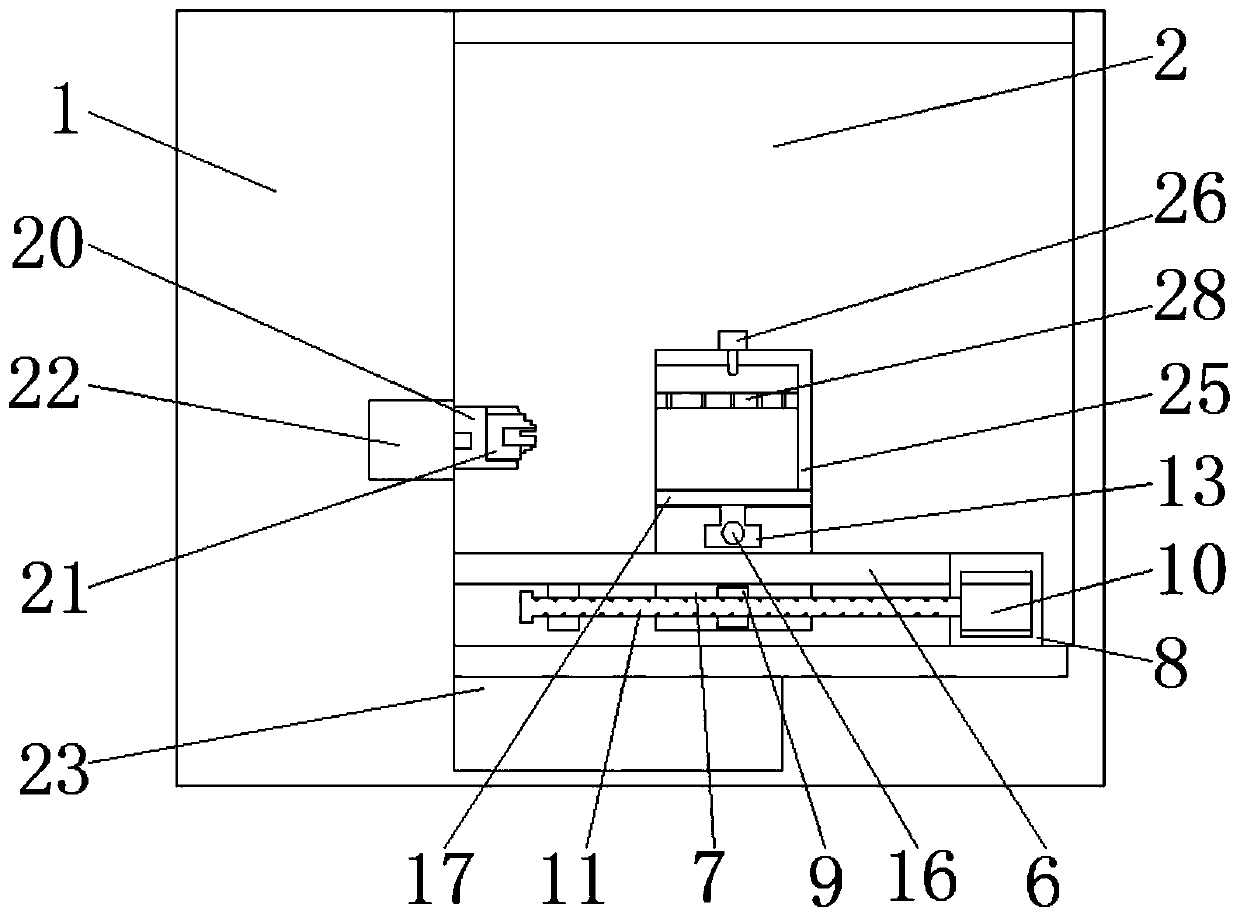
The invention discloses a numerical control detonator dissection machine tool and a dissection method thereof. The machine tool comprises a numerical control machine body, and a dissection machine body fixedly mounted on the side surface; the numerical control machine body is integrated with the dissection machine body; a digital system is positioned in the digital machine body, and is provided with a key area and a display area; the side surface of the numerical control machine body is electrically connected with an electronic hand vein through an electric wire; a slide rail is fixedly mounted in the dissection machine body, and a Z axle is in the direction of the slide rail; a slide sleeve slidingly sleeves the slide rail; a first chassis is fixedly mounted at one end of the slide rail;and the bottom of the first chassis is fixedly connected with the bottom of an inner cavity of the dissection machine body. A tool bit is adjusted to move on the Z axle and an X axle through a first motor and a second motor by the electronic hand vein; the position of the tool bit is adjusted to correspond to the positions of fixed detonators; then, a rotating motor is started to rotate the detonators; a cutter is controlled to dissect the detonators during moving on the X axle, so that the operation is simple and convenient; and the manual touch of the detonators is not needed during dissecting, so that the safety is guaranteed.

Description


Claims


Application Information

Patent Timeline
Owner CHINA COAL TECH & ENG GRP HUAIBEIBLASTING TECHN RES INST
Learn More