Cutting tool

A cutting tool and blade technology, applied in the field of cutting tools, can solve problems such as low cutting precision, difficulty in machining deep grooves, lateral offset, etc., and achieve the effects of reduced processing costs, high use value, and stable structure

Inactive Publication Date: 2019-05-21
江苏扬碟钻石工具有限公司
View PDF3 Cites 0 Cited by
  • Summary
  • Abstract
  • Description
  • Claims
  • Application Information

AI Technical Summary

Problems solved by technology

[0002] At this stage, most of the cutting blades with end face annular grooves (small groove width 0.5-2mm) on the market at this stage set the blade body (inscribed circle) as a straight line, so that during the production process of the blade, the strength of the blade will change with the width of the groove. The narrower the tool, the lower the strength of the tool. The narrower the tool, the more difficult it is to process deep grooves. Most of the existing tools are fixed by two screw holes. It is very inconvenient to change the blade, and the small screw is easy to lose, which not only increases the processing cost of the blade. , but also bring great inconvenience to people's life
[0003] Moreover, the tool holder on the traditional cutting tool, during the cutting process of the user, the cutting blade is likely to vibrate on the tool holder and shift laterally, resulting in low cutting accuracy and poor user experience

Method used


Image

  • Cutting tool
  • Cutting tool
  • Cutting tool

Examples


Embodiment Construction

[0018] The present invention will be described in further detail below in conjunction with the accompanying drawings.

[0019] It should be noted that all directional indications (such as up, down, left, right, front, back...) in the embodiments of the present invention are only used to explain the relative relationship between the various components in a certain posture (as shown in the drawings). When the positional relationship, movement conditions, etc., if the specific posture changes, the directional indication will also change accordingly. In addition, the technical solutions of the various embodiments can be combined with each other, but it must be based on the realization of those skilled in the art. When the combination of technical solutions is contradictory or cannot be realized, it should be considered that the combination of technical solutions does not exist , nor within the scope of protection required by the present invention.

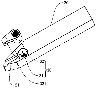
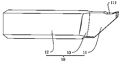
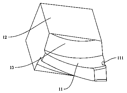
[0020] refer to figure 1 , ...


PUM


Abstract

The invention discloses a cutting tool which comprises a blade body, a tool rest and a fastening assembly. The blade body comprises a cutter body and an installation part; the middle part of the cutter body is arched outwards, so that the cutter body is in a circular arc shape as a whole; the upper end surface and the lower end surface of the cutter body are set as different thicknesses; the thicknesses are increased step by step from the lower end surface to the upper end surface; a placement groove for placing the installation part is formed in the tool rest; the fastening assembly is arranged on the tool rest and is used for pressing and fixing the installation part into the placement groove. Not only is the strength of a blade during the cutting process improved, but also the materialis further saved at the same time, the processing cost of the blade is greatly reduced, and the blade has a high use value on the market; meanwhile, the installation part is pressed and fixed into theplacement groove through the fastening assembly, so that the blade body is not easy to shake and laterally shift on the tool rest during the cutting process; and the cutting tool is stable in structure, good in performance and high in precision.

Description

technical field [0001] The invention relates to the field of metal cutting, in particular to a cutting tool. Background technique [0002] At this stage, most of the cutting blades (small groove width 0.5-2mm) end circular groove cutting blades on the market set the blade body (inscribed circle) as a straight line, so that during the production process of the blade, the strength of the blade will change with the width of the groove. The narrower the tool, the lower the strength of the tool. The narrower the tool, the more difficult it is to process deep grooves. Most of the existing tools are fixed by two screw holes. It is very inconvenient to change the blade, and the small screw is easy to lose, which not only increases the processing cost of the blade. , It also brings great inconvenience to people's life. [0003] Moreover, the tool holder on the traditional cutting tool, during the cutting process of the user, the cutting blade is likely to vibrate on the tool holder ...

Claims


Application Information

Patent Timeline
Patent Type & Authority Applications(China)
IPC IPC(8): B23B27/00B23B27/16
Inventor 唐健郑敏利姜彬陈涛李哲张为王波
Owner 江苏扬碟钻石工具有限公司
Why Eureka
Try Eureka