a water dispenser

A water dispenser and water bucket technology, which is applied to beverage preparation devices, kitchen utensils, home utensils, etc., can solve the problems of high power consumption of hot water machines, high starting frequency of thermal resistance, and more space for water dispensers, so as to avoid excessive liquid level. low effect

Inactive Publication Date: 2021-08-10
陈洛斌
View PDF6 Cites 0 Cited by
  • Summary
  • Abstract
  • Description
  • Claims
  • Application Information

AI Technical Summary

Problems solved by technology

[0002] Existing as figure 2 In the water dispensers shown, the hot water in the hot water tank and the cold water in the cold water tank flow in series, which causes the water temperature in the hot water tank to drop rapidly, so that the thermal resistance has a high starting frequency and is in the working state for a long time, resulting in The power consumption of the hot water machine is relatively high; the invention patent with the patent number of 201310322821.2 provides a technical solution aimed at solving this problem, mainly by adding a warm water tank so that the water pressure caused by the temperature change of the hot water tank when heating The fluctuation drives the water flow between the hot water tank and the warm water tank to prevent heat from spreading to the cold water tank. However, the warm water tank is used as a buffer space, which not only makes the water dispenser take up more space as a whole, but also the warm water tank must have excellent thermal insulation performance to To prevent its own heat loss, and to a certain extent, the warm water tank is another cold water tank, and it is also difficult to avoid problems caused by the thermal resistance in the hot water tank working for a long time

Method used


Image

  • a water dispenser
  • a water dispenser
  • a water dispenser

Examples


Embodiment Construction

[0019] The present invention will be further described below in conjunction with accompanying drawing of description and embodiment:

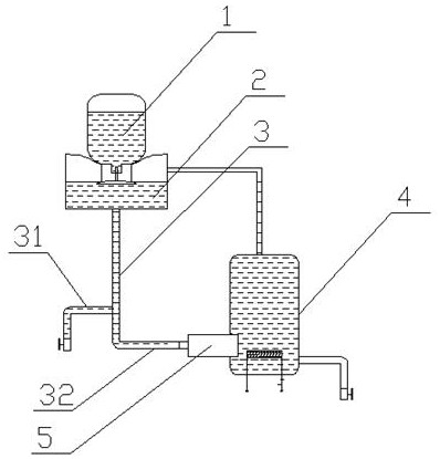
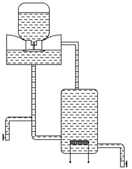
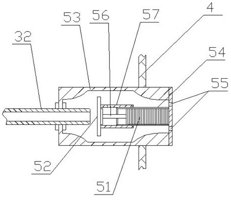
[0020] Such as figure 1 , image 3 The shown water dispenser includes a bucket 1, a cold water tank 2, an outlet pipe 3 and a hot water tank 4. The upper end of the cold water tank 2 is provided with a smart seat with a built-in smart head, and the bucket is connected to the cold water tank via the smart seat; the cold water tank The lower part of the outlet pipe is connected to the upper end of the outlet pipe; the lower branch of the outlet pipe 3 forms two branches, namely the first branch 31 and the second branch 32, and the first branch is connected to the water outlet valve to form a cold water outlet; the second branch The side wall of the hot water tank is connected with a hot water outlet pipe; the second branch road is connected to the hot water tank via the anti-hot water return unit 5, and the anti-hot water return unit 5 Built-i...


PUM


Abstract

The invention relates to a water dispenser, comprising a bucket, a cold water tank, a water outlet pipe and a hot water tank. A smart seat with a built-in smart head is arranged at the upper end of the cold water tank, and the water bucket is connected to the cold water tank through the smart seat; The upper end of the outlet pipe is connected; the lower branch of the outlet pipe forms two branches, namely the first branch and the second branch. The first branch is connected to the water outlet valve to form a cold water outlet; the second branch is connected to the hot water tank, Cold water is supplied in the water tank; the side wall of the hot water tank is connected with a hot water outlet pipe; the second branch is connected to the hot water tank through a hot water backflow prevention unit, and the hot water backflow prevention unit has a built-in thermal expansion element, which is connected to the A valve plate, the valve plate is opposite to the port of the second branch; when the heated expansion element is heated, the expansion drives the valve plate to move towards the port of the second branch, thereby blocking the port of the second branch, so that the second branch Disconnect from the hot water tank to avoid backflow of hot water into the cold water tank.

Description

technical field [0001] The invention relates to a water dispenser. Background technique [0002] Existing as figure 2 In the water dispensers shown, the hot water in the hot water tank and the cold water in the cold water tank flow in series, which causes the water temperature in the hot water tank to drop rapidly, so that the thermal resistance has a high starting frequency and is in the working state for a long time, resulting in The power consumption of the hot water machine is relatively high; the invention patent with the patent number of 201310322821.2 provides a technical solution aimed at solving this problem, mainly by adding a warm water tank so that the water pressure caused by the temperature change of the hot water tank when heating The fluctuation drives the water flow between the hot water tank and the warm water tank to prevent heat from spreading to the cold water tank. However, the warm water tank is used as a buffer space, which not only makes the water d...

Claims


Application Information

Patent Timeline
Patent Type & Authority Patents(China)
IPC IPC(8): A47J31/00A47J31/44A47J31/46
Inventor 陈洛斌
Owner 陈洛斌
Why Eureka
Try Eureka