Robot servo control method, device and robot
A technology of servo control and robotics, applied in the field of robotics, can solve the problems of servo control precision constraints, PID control overshoot and time lag, etc.
- Summary
- Abstract
- Description
- Claims
- Application Information
AI Technical Summary
Problems solved by technology
Method used
Image
Examples
Embodiment 1
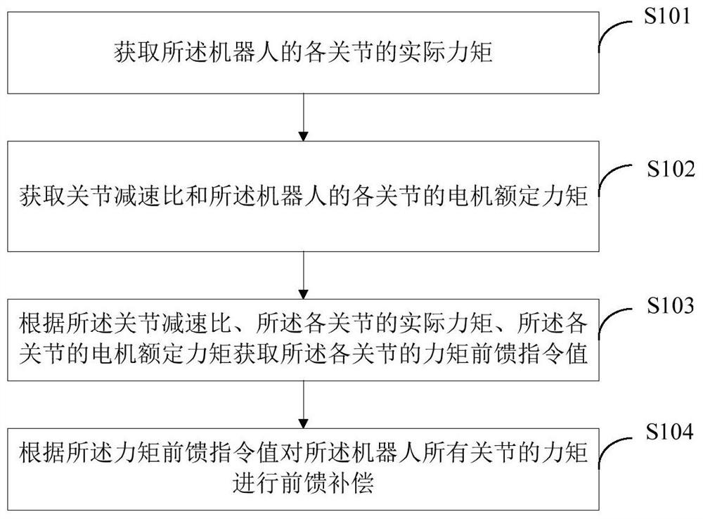
[0046] Such as figure 1 As shown, this embodiment provides a servo control method for a robot, which can be applied to terminal devices such as mobile phones, PCs, tablet computers, and robots. The servo control method of the robot provided in this embodiment includes:
[0047] S101. Obtain the actual moment of each joint of the robot.
[0048] In a specific application, the actual torque of each joint of the robot is obtained through the inverse dynamics equation. Specifically, the position, velocity, and acceleration of each joint of the robot under the current trajectory are calculated according to the inverse dynamics equation, and each joint of the robot is obtained. The actual moment of the joint.
[0049] S102. Obtain the reduction ratio of the joints and the rated torque of the motors of each joint of the robot.
[0050] In a specific application, the joint reduction ratio of each joint and the preset motor rated torque of each joint of the robot are obtained throug...
Embodiment 2
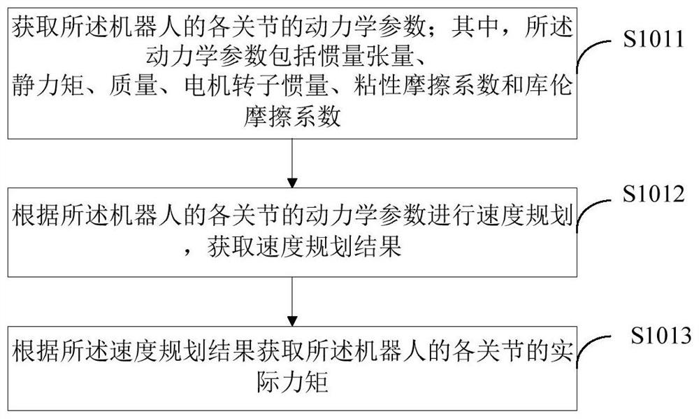
[0062] Such as figure 2 As shown, this embodiment is a further description of the method steps in the first embodiment. In this embodiment, step S101 includes
[0063] S1011. Obtain the dynamic parameters of each joint of the robot; wherein the dynamic parameters include inertia tensor, static moment, mass, motor rotor inertia, viscous friction coefficient and Coulomb friction coefficient;
[0064] In a specific application, the dynamic parameters of each joint of the robot are obtained through the dynamic parameter identification method (or directly obtain the preset dynamic parameters), where the dynamic parameters include but not limited to the inertia tensor, static moment, mass, motor Rotor inertia, viscous and Coulomb friction coefficients in the friction model. The static moment includes the static moment of the joint in the three directions of the X axis, the Y axis and the Z axis (ie MX, MY, MZ).
[0065] S1012. Perform speed planning according to the dynamic para...
Embodiment 3
[0074] Such as image 3 As shown, this embodiment is a further description of the method steps in the first embodiment. In this embodiment, step S104 includes:
[0075] S1041. Send the torque feedforward command value to the torque feedforward port;
[0076] In a specific application, the torque feed-forward command value obtained through calculation is sent to the torque feed-forward port to adjust the torque of each joint of the robot.
[0077] S1042. Control the torque feed-forward port to perform feed-forward compensation for the torques of all joints of the robot according to the torque feed-forward command value.
[0078] In a specific application, the control torque feedforward port performs feedforward compensation on the torque of the corresponding joints according to the torque feedforward command value, even if the actual torque of all joints of the robot is equal to the corresponding torque feedforward command value.
[0079] In this embodiment, the torque feed-...
PUM
 Abstract
Description
Claims
Application Information
 - R&D
- Intellectual Property
- Life Sciences
- Materials
- Tech Scout
- Unparalleled Data Quality
- Higher Quality Content
- 60% Fewer Hallucinations
Browse by: Latest US Patents, China's latest patents, Technical Efficacy Thesaurus, Application Domain, Technology Topic, Popular Technical Reports.
© 2025 PatSnap. All rights reserved.Legal|Privacy policy|Modern Slavery Act Transparency Statement|Sitemap|About US| Contact US: help@patsnap.com


