
Elastic sheet and electronic equipment

A shrapnel, elastic arm technology, applied in the direction of circuit, clamping/spring connection, fixed connection, etc., can solve the problems of crowding the antenna clearance distance, contact head pressure damage, affecting the antenna performance, etc., to reduce the clearance size, extend the Service life, the effect of improving the performance of the antenna

Pending Publication Date: 2019-05-14
SHANGHAI LONGCHEER TECH CO LTD
View PDF0 Cites 3 Cited by
  • Summary
  • Abstract
  • Description
  • Claims
  • Application Information

AI Technical Summary

Problems solved by technology

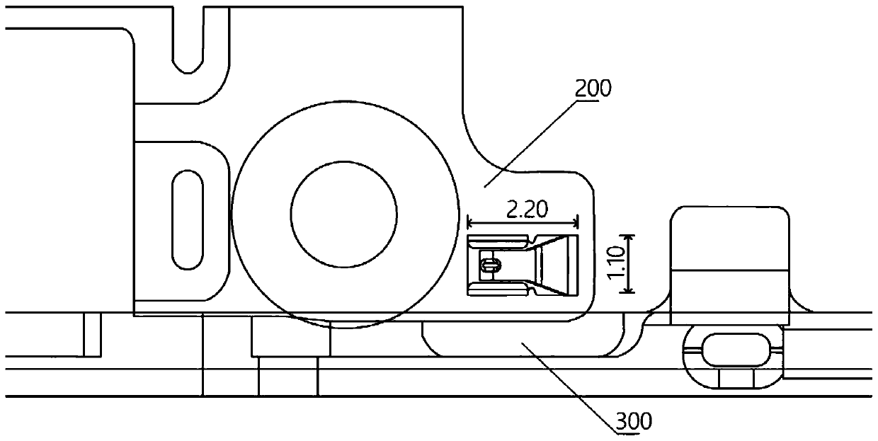
[0003] In the prior art, see figure 1 As shown, the shrapnel can be arranged horizontally, but this arrangement requires a large structural space and will cause the contact head to be damaged under pressure
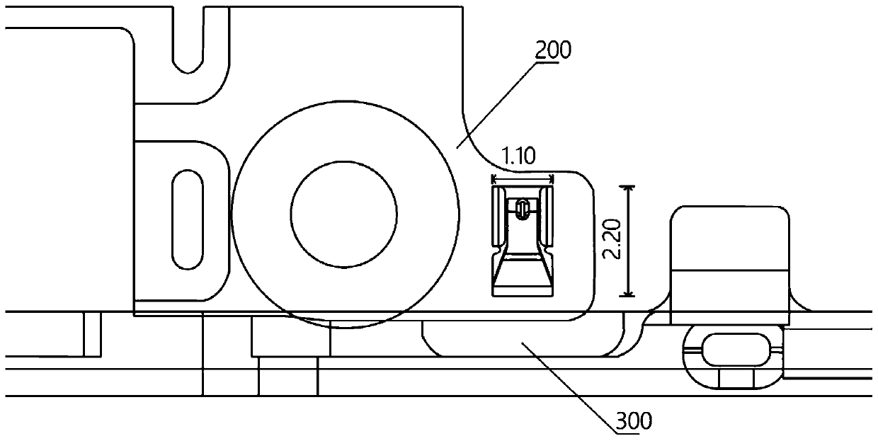
see figure 2 As shown, the contact head of the shrapnel can also be set towards the edge of the main board, but due to the existence of protruding structures such as the USB and earphone jacks, the PCB circuit board needs to be inserted obliquely into the front case of the mobile phone during assembly, so during the assembly process, when When the contact head of the shrapnel is set towards the edge of the PCB circuit board, the contact head is easily deformed by the reverse force exerted by the contact surface of the front shell, so it is easy to crush the shrapnel during assembly, resulting in poor contact
[0004] In addition, the size of conventional shrapnel is usually 2.2mm*1.1mm, and in order to ensure effective contact, the contact area between the metal frame and the shrapnel is usually a circle larger than the shrapnel, which makes the raised structure of the metal frame occupy the antenna clearance distance, Affected antenna performance

Method used


Image

  • Elastic sheet and electronic equipment
  • Elastic sheet and electronic equipment
  • Elastic sheet and electronic equipment

Examples


Embodiment Construction

[0036] The idea, specific structure and technical effects of the present application will be further described below in conjunction with the accompanying drawings, so as to fully understand the purpose, features and effects of the present application.

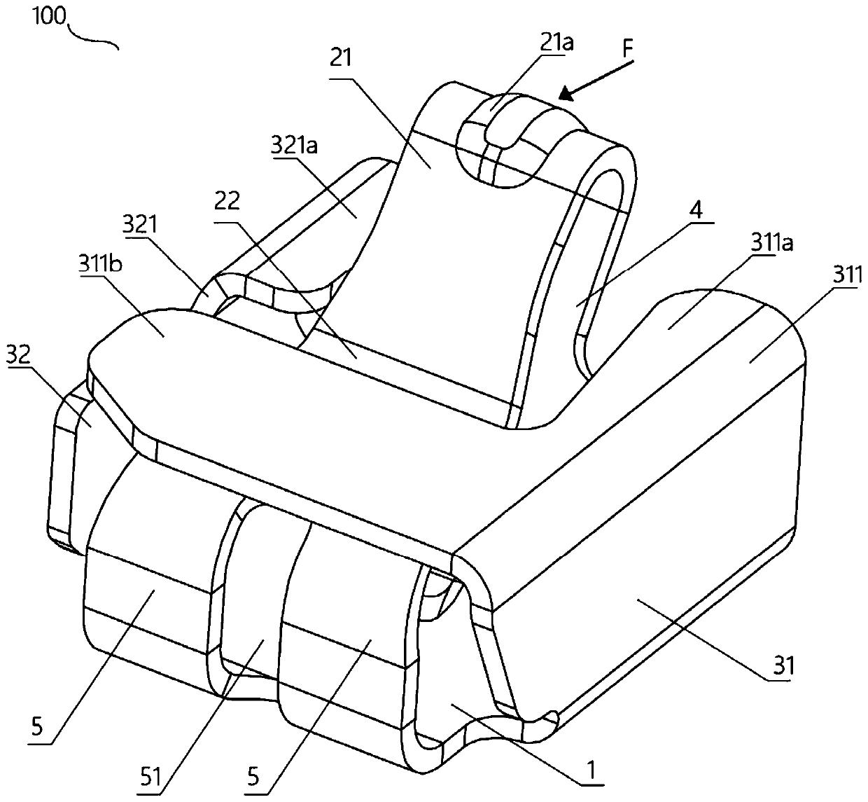
[0037] Such as image 3 and Figure 4 As shown, the elastic piece 100 of this embodiment includes: a base 1, the first side and the second side of the base 1 are respectively provided with a first protection part 31 and a second protection part 32; and an elastic arm, the The elastic arm is connected to the third side of the base 1; wherein, the elastic arm is provided with a contact head 21a protruding relative to the elastic arm; when an external force is applied to the contact head 21a, the The elastic arm is set close to the base 1; when the external force disappears, the elastic arm is set away from the base 1.

[0038] The first protection part 31 and the second protection part 32 provided in this embodiment can reduce ...


PUM


Abstract

The invention belongs to the technical field of electronic equipment, and particularly relates to an elastic sheet and electronic equipment. The elastic sheet comprises a base and an elastic arm, wherein a first protection part and a second protection part are respectively arranged at a first side edge and a second side edge of the base, the elastic arm is connected with a third side edge of the base, a contact head is arranged on the elastic arm and protrudes relative to the elastic arm, the elastic arm is arranged near to the base when an external force is applied to the contact head, and the elastic arm deviates from the base when the external force disappears. The electronic equipment comprises the elastic sheet, wherein the elastic sheet is arranged on a PCB and is in contact with a gold finger on a metal frame. The elastic sheet is simple to process and manufacture, is stable to use and is relatively good in reliability and relatively small in size, the size of a protruding structure of the metal frame can be obviously reduced, the occupancy clearance size of an antenna is reduced, and the antenna performance is improved.

Description

technical field [0001] The application belongs to the technical field of electronic equipment, and in particular relates to a shrapnel and electronic equipment. Background technique [0002] At present, electronic devices such as smartphones use metal frames as antennas, which has become the main development trend. The metal frame and the circuit on the motherboard are usually connected by shrapnel. Therefore, a raised structure needs to be made on the metal frame to contact the contact head of the shrapnel. [0003] In the prior art, see figure 1 As shown, the shrapnel can be arranged laterally, however, this arrangement requires a large structural space and will cause the contact head to be damaged under pressure. see figure 2 As shown, the contact head of the shrapnel can also be set towards the edge of the main board, but due to the existence of protruding structures such as the USB and earphone jacks, the PCB circuit board needs to be inserted obliquely into the fron...

Claims


Application Information

Patent Timeline
Patent Type & Authority Applications(China)
IPC IPC(8): H01R12/57H01R4/48H01R4/64H01Q1/50
Inventor 王洪军杜军红汤肖迅
Owner SHANGHAI LONGCHEER TECH CO LTD
Learn More