
Magnon magnetoresistance and spin Hall magnetoresistance devices based on magneton valves and magneton junctions

A technology of spin Hall and spin Hall effect, which is applied in the field of magnetic devices and can solve problems such as Joule heat

Active Publication Date: 2021-07-09
INST OF PHYSICS - CHINESE ACAD OF SCI
View PDF0 Cites 0 Cited by
  • Summary
  • Abstract
  • Description
  • Claims
  • Application Information

AI Technical Summary

Problems solved by technology

[0003] Traditional GMR and TMR devices affect the transport properties of the device through the spin of carriers—electrons, although they have made great achievements in the fields of traditional spintronics, such as computer hard disk heads and magnetic random access memories. Successful, but there is still room for further innovation and development of these devices
Their biggest defect is that the operation of the device is accompanied by the movement of the spin carrier-electrons, which will generate Joule heat, which is the largest source of power consumption for existing microelectronic devices

Method used


Image

  • Magnon magnetoresistance and spin Hall magnetoresistance devices based on magneton valves and magneton junctions
  • Magnon magnetoresistance and spin Hall magnetoresistance devices based on magneton valves and magneton junctions
  • Magnon magnetoresistance and spin Hall magnetoresistance devices based on magneton valves and magneton junctions

Examples


Embodiment Construction

[0023] Exemplary embodiments of the present invention will be described below with reference to the accompanying drawings. Note that the drawings may not be drawn to scale.

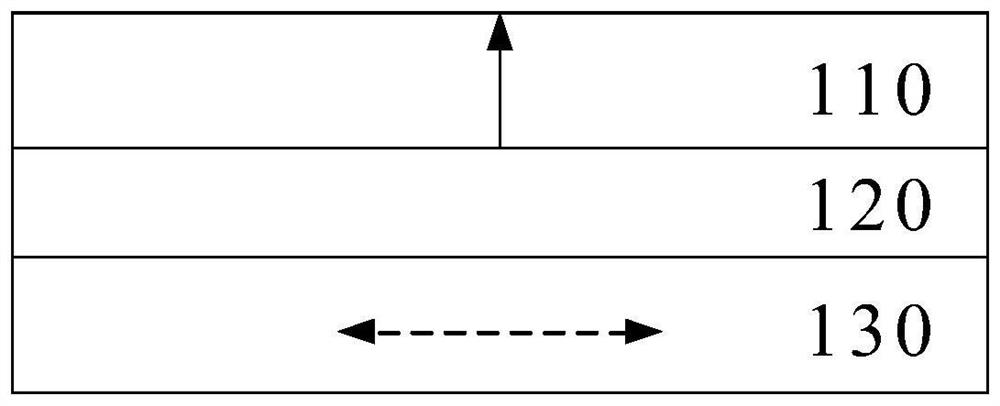
[0024] figure 1 is a schematic diagram of the layer structure of a magneton magnetoresistance (MMR) device 100 according to an exemplary embodiment of the present invention. Such as figure 1 As shown, the MMR device 100 includes a first magnon-conducting layer 110 , a second magnon-conducting layer 130 , and an intermediate spacer layer 120 between them.

[0025] Each of the first magneton-conducting layer 110 and the second magneton-conducting layer 130 may be formed of a magnetic insulating material, preferably a ferromagnetic insulating material, examples of which include but are not limited to: R 3 Fe 5 o 12 , where R can be Y, Pr, Nd, Sm, Eu, Gd, Tb, Dy, Ho, Er, Tm, Yb and Lu; MFe 2 o 4 , where M can be Mn, Zn, Cu, Ni, Mg, and Co; and Fe 3 o 4 、BaFe 12 o 19 , SrFe 12 o 19 Wait.

[0026]...


PUM


Abstract

The invention relates to a magneton magnetoresistance device and a spin Hall magnetoresistance device based on a magneton valve and a magneton junction. According to an embodiment, a magneton magnetoresistive device may include: a first magneton conduction layer; a second magneton conduction layer disposed on the first magneton conduction layer; and a second magneton conduction layer disposed on the first magneton conduction layer; An intermediate layer between the conduction layer and the second magneton conduction layer, wherein the first magneton conduction layer and the second magneton conduction layer are formed of a magnetic insulating material, and the intermediate layer is formed of a non-magnetic metal or antiferromagnetic insulators or antiferromagnetic metallic materials.

Description

technical field [0001] The present invention generally relates to the field of magnetic devices, and more particularly relates to a magneton magnetoresistance device based on a magneton valve and a magneton junction and a spin Hall magnetoresistance device including a magneton magnetoresistance device. Background technique [0002] Since the discovery of tunneling magnetoresistance (TMR) in Fe / Ge / Co multilayers in 1975 and giant magnetoresistance (GMR) in magnetic multilayers in 1988, physics and materials in spintronics Scientific research and applications have made great progress, especially the tunneling transport properties of spin-related electrons in magnetic tunnel junctions and the tunneling magnetoresistance effect have become one of the important research fields in condensed matter physics. In 1995, Miyazaki et al. and Moodera et al. discovered the high room temperature tunneling magnetoresistance effect in "ferromagnetic metal / Al-O insulating barrier / ferromagnetic...

Claims


Application Information

Patent Timeline
Patent Type & Authority Patents(China)
IPC IPC(8): H01L43/08H01L43/06H01L43/10H10N50/10H10N52/00
Inventor 韩秀峰郭晨阳万蔡华
Owner INST OF PHYSICS - CHINESE ACAD OF SCI
Learn More