Eureka AIR delivers breakthrough ideas for toughest innovation challenges, trusted by R&D personnel around the world.

Low-pressure shunting device

A shunt device, low-pressure technology, applied in the field of low-pressure shunt device, shunt device of aluminum alloy low-pressure casting process, can solve the problems of shunt device sticking to aluminum, long disassembly time, blockage, etc., to improve versatility and interchangeability , Reduce processing difficulty, reduce the effect of using cost

Pending Publication Date: 2019-05-14
XINXING HEAVY IND HUBEI 3611 MECHANICAL
View PDF0 Cites 4 Cited by
  • Summary
  • Abstract
  • Description
  • Claims
  • Application Information

AI Technical Summary

Problems solved by technology

On the one hand, the existing low-pressure shunt device is usually directly connected and fixed on the lower mold by bolts, and a circle of bolts is required for disassembly and assembly, which takes a long time and is inconvenient
On the other hand, during the production process of the shunt device, aluminum liquid is repeatedly flushed, and the shunt device is easy to stick to aluminum and cause blockage, resulting in short service time and high maintenance frequency

Method used


Image

  • Low-pressure shunting device
  • Low-pressure shunting device
  • Low-pressure shunting device

Examples


Embodiment Construction

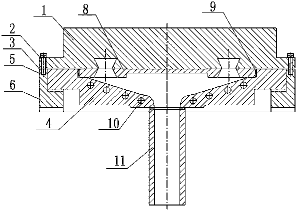
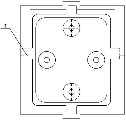
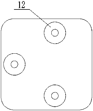
[0019] figure 1 , 2 , 3, 4, the present invention includes connection frame 6, diversion basin 4, diversion cover 8, bolt 3, asbestos pad 9, heating pipe 10 and so on. The connecting frame 6 is provided with positioning grooves 7 matched with the distribution basin 4 on the periphery. There are three upper cylindrical bosses 12 on the outer wall of the diverter cover 8, and three lower cylindrical bosses 13 in the inner cavity. A heating pipe hole 10 is arranged on the distribution basin 4 . A positioning space for positioning with the mold body is formed between the three upper cylindrical bosses 12 .

[0020] When installing, first put the asbestos pad 9 into the inner wall of the distribution basin 4, and then press the distribution cover 8 into the groove of the distribution basin 4. The height of the upper cylindrical boss 12 of the distribution cover 8 after assembly is higher than that of the distribution basin. 4 on the plane. After installing, put the protruding ...


PUM


Abstract

The invention provides a low-pressure shunting device. The low-pressure shunting device comprises a connecting frame, a shunting basin and a shunting cover, wherein the connecting frame, the shuntingbasin and the shunting cover are connected with a mold body. The upper end of the shunting basin extends outwards to form two or more protruding blocks, and the shunting basin is movably installed ina positioning groove of the connecting frame through the protruding blocks. The shunting cover is installed at a basin port at the upper end of the shunting basin through an asbestos pad, the shuntingcover is provided with bosses, and a water inlet corresponding to a sprue of the mold body is formed among the bosses; and the bosses comprise one or more lower cylindrical bosses arranged on the inner wall of the shunting cover and one or more cylindrical bosses arranged on the outer wall of the shunting cover, and the lower end of the shunting basin is provided with a liquid inlet correspondingly matched with a liquid lifting tube. The low-pressure shunting device mainly aims at solving the problems that during low-pressure aluminum-alloy metal mold casting, paint spraying, maintenance andcleaning operation of the shunting device are long in time and inconvenient. According to the low-pressure shunting device, operation can be conducted without disassembling a mold, and inner-cavity stuck aluminum cleaning is convenient to achieve.

Description

technical field [0001] The invention relates to a low-pressure shunt device, in particular to a shunt device used in an aluminum alloy low-pressure casting process, and belongs to the field of aluminum alloy casting process equipment. Background technique [0002] At present, in the aluminum alloy low-pressure casting process, the low-pressure equipment generally only has 1-3 liquid rising ports and the liquid rising ports are on the same straight line. For aluminum alloy parts with a relatively complex structure, it is usually necessary to open multiple gates in different parts for feeding. Multi-gate casting. On the one hand, the existing low-pressure shunt device is usually directly connected and fixed on the lower mold by bolts, and it needs to install and remove a circle of bolts for disassembly and assembly, which takes a long time and is inconvenient. On the other hand, during the production process of the shunt device, aluminum liquid is repeatedly flushed, and the...

Claims


Application Information

Patent Timeline
Patent Type & Authority Applications(China)
IPC IPC(8): B22D18/04
Inventor 刘海军陈家木夏贵光郑飞
Owner XINXING HEAVY IND HUBEI 3611 MECHANICAL
Why Eureka
Eureka Blog
Learn More