Automatic wire rope breaking and riveting device

An automatic material cutting and riveting device technology, which is applied in the field of automation equipment, can solve the problems of difficult to guarantee the quality of steel cable production, difficult to realize automatic production, and difficult to fix the riveting position, so as to solve the problem of difficult to ensure the accuracy of feeding and solve the problem of replacement The effect of low material efficiency and reliable operation

Pending Publication Date: 2019-05-14
SICHUAN UNIV
View PDF1 Cites 0 Cited by
  • Summary
  • Abstract
  • Description
  • Claims
  • Application Information

AI Technical Summary

Problems solved by technology

Due to the complexity and the difficulty of automatic production, the current processing of wire ropes often adopts mechanical cutting, manual grinding, manual piercing butt joint, and manual placement of riveting. The production efficiency is low, the quality of wire rope production is difficult to guarantee, and the riveting position is difficult to fix
In order to ensure the production quality and realize the automatic production of steel cables, the application number CN105350366 has announced the integrated automatic processing machine for automobile cable wire ropes, which can realize the multi-process centralized processing of automatic feeding, cutting, patterning, die-casting and edge cleaning of automobile cable wire ropes. The workpieces are arranged at designated stations at intervals of 90 degrees by rotating pallets, and steel cables are connected by die-casting; the station equipment of this device is distributed in a circle, occupies a large area, has a complex structure and low processing flexibility, and can only realize Processing of fixed length wire rope

Method used


Image

  • Automatic wire rope breaking and riveting device
  • Automatic wire rope breaking and riveting device
  • Automatic wire rope breaking and riveting device

Examples


Embodiment Construction

[0019] The present invention is described in further detail below:

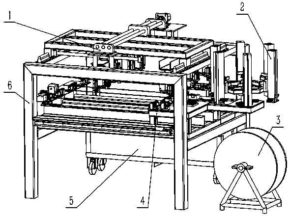
[0020] Such as figure 1 As shown, the frame 6 is the load-bearing foundation of the entire automation device, the transport mechanism 1 is installed on the top floor, the integrated workbench 4 is placed on the middle floor, the automatic feeding mechanism 2 is fixed on the feeding support platform 12 through the connecting plate 33, and the feeding The wire reel 3 and the finished product receiving box 5 are placed on the bottom; the comprehensive workbench 4 is composed of a mobile platform 7, a fixed platform 11, a feeding support platform 12, a workbench frame 15, a drag motor 17 and a guide rail 18, and the material is cut off. The mechanism 14, the chamfering mechanism 13, the piercing butt joint mechanism 10 and the riveting mechanism 9 are installed side by side on the fixed platform 11 in turn, and the dragging motor 17 is installed on the side of the workbench frame 15 close to the cutting mechanism...


PUM


Abstract

The invention discloses an automatic wire rope breaking and riveting device. The automatic wire rope breaking and riveting device comprises a transportation mechanism, an automatic supply mechanism, afeeding wire coil, a comprehensive workbench, a finished product receiving box, a rack and a control system. A wire rope is simultaneously machined by a breaking mechanism, a chamfering mechanism, aperforating abutting mechanism and a riveting mechanism which are sequentially arranged on the comprehensive workbench; a drag motor conveys the wire rope to the breaking station from the feeding wirecoil, a rope head is installed on a rope head mold through the automatic supply mechanism and then is conveyed to the perforating abutting station, and feeding of the wire rope and the rope head is achieved; and the wire rope on each station is clamped by a linkage pneumatic claw of the transportation mechanism, and the transportation mechanism travels to achieve material transfer and finished product discharging. The control system finishes automatic control over the process of wire rope dragging, breaking, chamfering, wire rope and rope head perforating abutting, riveting, finished productrecycling and transportation. The device is high in automation degree, simple and compact in structure and high in transportation efficiency and can automatically adapt to breaking, chamfering, perforating abutting and riveting of wire ropes of various lengths and diameters.

Description

technical field [0001] The invention relates to the technical field of automation equipment, in particular to an automatic cutting and riveting device for steel cables. Background technique [0002] With the rapid development of the automobile industry, the automation of processing auto parts has increased, and there are many types of auto parts. Automobile steel cables are widely used in braking, clutching, throttle adjustment and other aspects of automobiles. The connection between the cable head and the steel cable Usually riveted connection. Due to the complexity and the difficulty of automatic production, the current processing of steel cables often adopts mechanical cutting, manual grinding, manual perforation butt joint, and manual placement of riveting. The production efficiency is low, the quality of steel cable production is difficult to guarantee, and the riveting position is difficult to fix. . In order to ensure the production quality and realize the automatic...

Claims


Application Information

Patent Timeline
Patent Type & Authority Applications(China)
IPC IPC(8): B21F11/00B21F15/00B21F23/00B21F9/00
Inventor 熊瑞平乔治罗勇舒生豪王波程昶运邓银
Owner SICHUAN UNIV
Why Eureka
Try Eureka