Eureka AIR delivers breakthrough ideas for toughest innovation challenges, trusted by R&D personnel around the world.

Acoustic emission/micro-seismic event location method under condition of cavity existence

A positioning method and acoustic emission technology, which is applied in seismology, seismic signal processing, complex mathematical operations, etc., can solve the problems of not considering the impact and positioning result errors, so as to break through the limitations of positioning results, reduce positioning errors, and avoid excessive Dependence on initial iteration values ​​and effects of non-convergence

Active Publication Date: 2019-05-10
NORTHEASTERN UNIV
View PDF3 Cites 8 Cited by
  • Summary
  • Abstract
  • Description
  • Claims
  • Application Information

AI Technical Summary

Problems solved by technology

Therefore, there is a space barrier between the crack position inside a large number of rock bodies and the sensor, and the stress wave induced by the rock mass fracture must bypass the space to propagate to the sensor position and be collected. The change of the wave propagation path and distance will be It leads to the change of the wave propagation time. Ignoring this influencing factor will lead to an increase in the error of the positioning result. However, the widely used positioning algorithm does not consider the influence of the empty area on the wave propagation path.

Method used


Image

  • Acoustic emission/micro-seismic event location method under condition of cavity existence
  • Acoustic emission/micro-seismic event location method under condition of cavity existence
  • Acoustic emission/micro-seismic event location method under condition of cavity existence

Examples


Embodiment

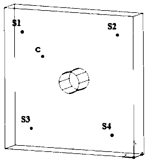
[0082] 1. Establish a three-dimensional solid geological model according to the actual situation, such as figure 1 As shown, it is assumed that there are four sensors S1, S2, S3, and S4, the actual acoustic emission / microseismic event c, and the sensor position coordinates are shown in Table 1.

[0083] Table 1

[0084]

[0085]

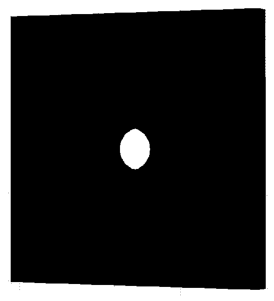
[0086] 2 pairs figure 1 Grid division of the 3D solid geological model, such as figure 2 shown.

[0087]3. Assign physical and mechanical parameter values ​​to grid units. For simplicity, a homogeneous medium with uniform lithology is used in this embodiment.

[0088] 4. Set the boundary conditions and apply instantaneous step force on the unit nodes in sequence, and the time interval of applying the instantaneous step force is 0.1s.

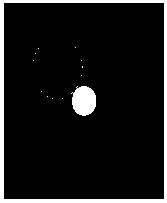
[0089] 5. Simulate the stress wave propagation process, and calculate the travel time of the stress wave to each sensor according to the simulation results (as shown in Figure 3). In the case of 4 sensors, e...


PUM


Abstract

The invention provides an acoustic emission / micro-seismic event location method under the condition of cavity existence. The acoustic emission / micro-seismic event location method overcomes the difficult problem that the locating accuracy is affected due to inaccurate wave velocity input under the influence of rock mass excavation, and can more precisely determine the space position of an acousticemission / micro-seismic event in a rock body by combining the numerical simulation of stress wave propagation on the basis of considering the influence during the rock projection excavation. By using aformed cavity form as the known condition, the change on the wave propagation path by the cavity, the resulted change of the wave propagation path and the retardation time of the wave reaching the sensor are quantized in cooperation with numerical simulation, thereby obviously reducing acoustic emission / micro-seismic event location errors induced by the cavity existence. In addition, a mesh search and error weight coefficient method is jointly used in the location algorithm, detects of excessive dependence on the initial iteration value and mis-convergence in the iterative algorithm are avoided, the limitation of mesh size to the location result is broken through.

Description

technical field [0001] The invention belongs to the technical field of acoustic emission / microseismic event positioning methods in mining, and relates to an acoustic emission / microseismic event positioning method under the condition of empty areas. Background technique [0002] The rapid growth of my country's economy has greatly stimulated the development of resources and energy, most of which involve rock engineering. The construction process of rock engineering will cause the formation of the internal fracture surface of the rock mass and the propagation of stress waves at the same time. This phenomenon is called acoustic emission (high frequency, small amplitude) or microseismic (low frequency, large amplitude). Acoustic emission / microseismic is an accompanying phenomenon of the rock mass fracture process, which is closely related to the physical and mechanical behavior of the rock mass. Therefore, the stress state and fracture degree of the rock mass can be inferred thr...

Claims


Application Information

Patent Timeline
IPC IPC(8): G01V1/00G01V1/30G06F17/50G06F17/16
Inventor 张鹏海杨天鸿魏晨慧朱万成于庆磊徐涛
Owner NORTHEASTERN UNIV
Why Eureka
Eureka Blog
Learn More