Positioning method of electromagnetic interference source in vehicle based on CAN bus data

A technology of CAN bus and electromagnetic interference, which is applied in the field of positioning electromagnetic interference sources in vehicles, can solve the problems of complex electromagnetic compatibility environment, prolonged research and development cycle, and expensive testing, so as to shorten the time of positioning and analysis, improve analysis efficiency, and ensure The effect of accuracy

Active Publication Date: 2019-05-10
SINO TRUK JINAN POWER
View PDF9 Cites 14 Cited by
  • Summary
  • Abstract
  • Description
  • Claims
  • Application Information

AI Technical Summary

Problems solved by technology

[0002] While vehicle power, economy, comfort, safety, and reduced pollutant emission levels are being improved, more and more electronic components are used in vehicles, resulting in an increasingly complex electromagnetic compatibility environment inside vehicles, especially In addition to the 12 / 24V low-voltage electronic components inside the hybrid, fuel cell and pure electric vehicles, high-voltage electronic components of up to several hundred volts are also installed, resulting in a worse electromagnetic environment for the vehicle, and the high-voltage electronic components cause serious electromagnetic damage to the low-voltage electronic components. Interference often causes low-voltage electronic components to fail to work properly
[0003] When the vehicle encounters electromagnetic compatibility problems, it usually sends samples of the problematic parts to the automotive electronic components electromagnetic compatibility laboratory for testing, and then analyzes the electromagnetic compatibility problem and locates the three elements through the test data, which not only makes the vehicle's Extended R&D cycle and increased R&D costs due to expensive EMC laboratory testing

Method used


Image

  • Positioning method of electromagnetic interference source in vehicle based on CAN bus data
  • Positioning method of electromagnetic interference source in vehicle based on CAN bus data
  • Positioning method of electromagnetic interference source in vehicle based on CAN bus data

Examples


Embodiment Construction

[0051] In order to clearly illustrate the technical features of the solution, the solution will be described below through specific implementation modes.

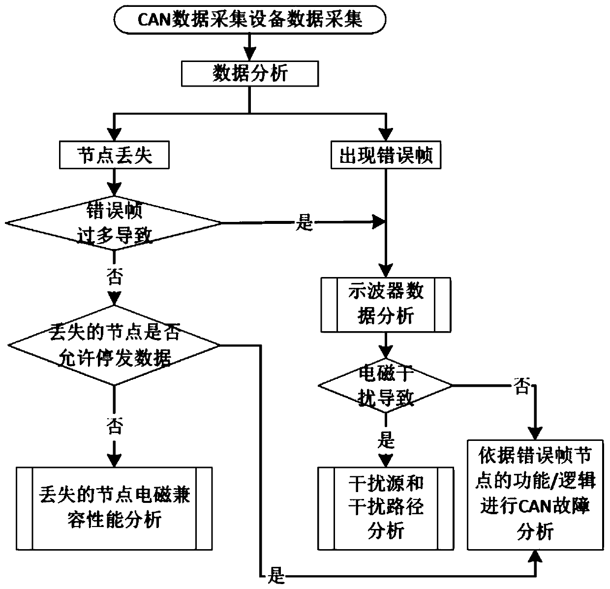
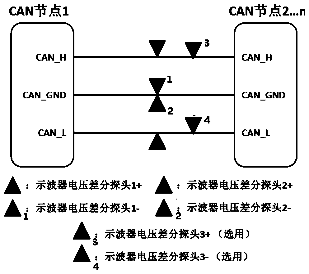
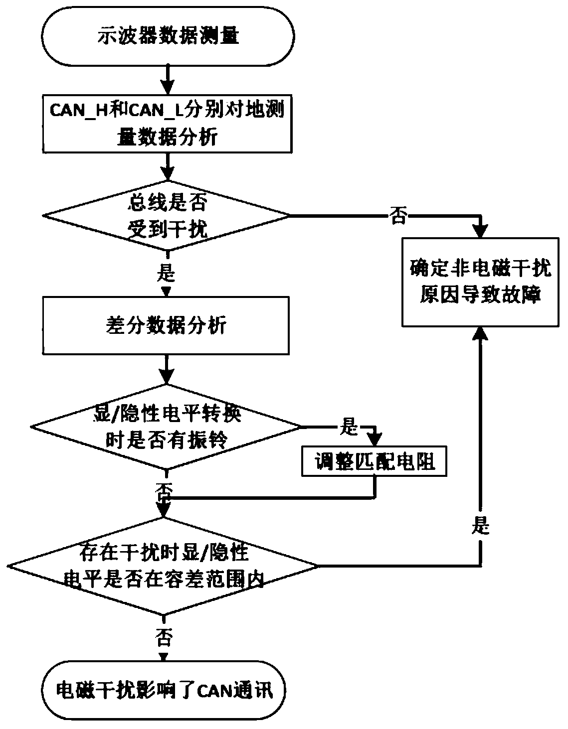
[0052] see Figure 1 to Figure 5 , the present invention is: a kind of location method that carries out the electromagnetic interference source in the vehicle based on CAN bus data, comprises the following steps:

[0053] Step 1: Use CAN bus data to locate the electromagnetic interference source in the vehicle, and collect data through CAN data acquisition equipment. If the node is not lost due to too many error frames and the node is allowed to automatically stop sending data if the conditions are met, judge If the condition is established, if it is established, the CAN fault analysis is performed through the function or logic of the vehicle and the node, otherwise, the electromagnetic compatibility analysis is required; if the node is not allowed to stop sending data and the node is lost, the electromagnetic compatibility...


PUM


Abstract

The invention provides a positioning method of an electromagnetic interference source in a vehicle based on CAN bus data, and belongs to the technical field of vehicle and electromagnetic compatibility. According to the technical scheme, the positioning method of the electromagnetic interference source in the vehicle based on the CAN bus data comprises the following steps that S1, CAN bus data acquisition equipment is used for data acquisition and analysis; S2, the electromagnetic compatibility of a node is analyzed; S3, oscilloscope measurement data is analyzed; S4, CAN faults are analyzed based on a function or logic of an error frame node; and S5, interference sources and interference paths are analyzed. The positioning method has the beneficial effects that efficiency of positioning the interference sources and interference paths to the CAN bus in the vehicle can be improved, the time of positioning and analyzing the electromagnetic compatibility problems in the vehicle is shortened, and accuracy of interference source positioning is guaranteed.

Description

technical field [0001] The invention relates to the technical field, in particular to a method for locating electromagnetic interference sources in vehicles based on CAN bus data. Background technique [0002] While vehicle power, economy, comfort, safety, and reduced pollutant emission levels are being improved, more and more electronic components are used in vehicles, resulting in an increasingly complex electromagnetic compatibility environment inside vehicles, especially In addition to the 12 / 24V low-voltage electronic components inside the hybrid, fuel cell and pure electric vehicles, high-voltage electronic components of up to several hundred volts are also installed, resulting in a worse electromagnetic environment for the vehicle, and the high-voltage electronic components cause serious electromagnetic damage to the low-voltage electronic components. Interference sometimes causes low-voltage electronic components not to work properly. [0003] When the vehicle encou...

Claims


Application Information

Patent Timeline
IPC IPC(8): G01R31/00H04L12/26H04L12/40
Inventor 李明强宋莉陈冲张绍楠
Owner SINO TRUK JINAN POWER
Why Eureka
Try Eureka