
Multi-stage acceleration electromagnetic gun experimental facility based on STM32 control

An experimental device and electromagnetic gun technology, which is applied in the direction of electromagnetic launchers, weapons without explosives, instruments, etc., can solve the problems of uncontrollable voltage, undisplayable exit speed, and insufficient coil magnetic field force, etc.

Pending Publication Date: 2019-05-10
ANHUI UNIV OF SCI & TECH
View PDF10 Cites 9 Cited by
  • Summary
  • Abstract
  • Description
  • Claims
  • Application Information

AI Technical Summary

Problems solved by technology

[0003] The existing electromagnetic gun model has the following disadvantages: 1. The voltage of the existing electromagnetic gun is fixed and cannot be adjusted, and the voltage when the capacitor is charged cannot be controlled, so that the speed and range of the shell cannot be adjusted; 2. , The energy storage capacitor bank is used for charging and discharging operations, but there is only one level of discharge circuit, the magnetic field force of the coil is not enough, and the speed of the shell will also be limited; 3. The speed of the shell cannot be displayed

Method used


Image

  • Multi-stage acceleration electromagnetic gun experimental facility based on STM32 control
  • Multi-stage acceleration electromagnetic gun experimental facility based on STM32 control
  • Multi-stage acceleration electromagnetic gun experimental facility based on STM32 control

Examples


Embodiment Construction

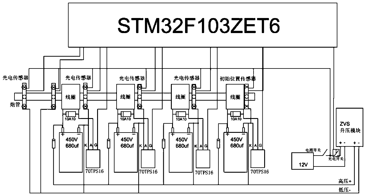
[0015] Refer to the attached figure 1 As shown, the present invention is a multi-stage accelerated electromagnetic gun experimental device based on STM32 control, which is characterized in that: the experimental device includes a STM32F103ZET6 main control module, a photoelectric sensor, an execution device, a speed measurement module, a liquid crystal display module, and a main control chip Power supply module, transmitter power supply module, ZVS booster module, launch button and voltage detection module.

[0016] The positions before the 2nd stage electromagnetic gun coil, before the 3rd stage electromagnetic gun coil, and before the 4th stage electromagnetic gun coil are all equipped with a position detection module, and the position detection is carried out after the projectile passes through the first stage electromagnetic gun coil. When the projectile reaches the coil of the second-stage electromagnetic gun, the position information collected by the photoelectric sensor...


PUM


Abstract

The invention discloses a multi-stage acceleration electromagnetic gun experimental facility based on STM32 control. The multi-stage acceleration electromagnetic gun experimental facility based on STM32 control is characterized by comprising an STM32F103ZET6 master control module, a power module, a boosting module, a sensor module, a speed measurement module, a liquid crystal display module, a launching module, a shell initial position detection module and a voltage detection module. According to the multi-stage acceleration electromagnetic gun experimental facility based on STM32 control, a multi-stage acceleration coil on a trajectory, and therefore, the number of acceleration stages can be chosen as needed; and meanwhile, because a photoelectric sensor is installed on a gun barrel to detect the position of a shell, a signal is transmitted to a master control chip, and then the master control chip controls a capacitor of a next stage to discharge. According to the multi-stage acceleration electromagnetic gun experimental facility based on STM32 control, by adopting the structure, a user can choose the number of acceleration stages as needed through the STM32, the charging voltageof the capacitors can be controlled as needed as well, the muzzle velocity and the firing range of the shell can be controlled, and the muzzle velocity can be measured; and because of OLED display, other data in experiments can be acquired at the same time as well, and physics teaching experiments are convenient to carry out.

Description

technical field [0001] The invention relates to an electromagnetic gun experimental device, in particular to a multi-stage accelerated electromagnetic gun experimental device based on STM32 control. Background technique [0002] An electromagnetic gun is an advanced high-energy weapon that uses electromagnetic fields to convert electrical energy into kinetic energy of shells. It can not only use ultra-high kinetic energy to kill and destroy targets, but also add ammunition to attack targets. Compared with traditional artillery and rocket launches, electromagnetic guns have significant advantages such as smaller launch noise, good concealment, and high ejection velocity, and have become a research hotspot in the military field in recent years. [0003] The existing electromagnetic gun model has the following disadvantages: 1. The voltage of the existing electromagnetic gun is fixed and cannot be adjusted, and the voltage when the capacitor is charged cannot be controlled, so ...

Claims


Application Information

Patent Timeline
Patent Type & Authority Applications(China)
IPC IPC(8): F41B6/00G09B25/00
Inventor 甘福宝黄友锐徐善永张小乐张越张超
Owner ANHUI UNIV OF SCI & TECH
Learn More