
Isolation and shielding device and method for valve internal leakage

A shielding device and valve technology, applied in pipeline systems, gas/liquid distribution and storage, mechanical equipment, etc., can solve problems such as escape, valve life reduction, combustion, etc., to achieve high judgment accuracy, good shielding effect, and investment. low cost effect

Active Publication Date: 2021-08-17
XINJIANG DAQO NEW ENERGY
View PDF0 Cites 0 Cited by
  • Summary
  • Abstract
  • Description
  • Claims
  • Application Information

AI Technical Summary

Problems solved by technology

Since the valve is subjected to various harsh environments such as temperature, pressure, wear and corrosion during operation, generally the valve cannot achieve 100% leak-free sealing, which will lead to leakage, resulting in run-off, combustion, explosion, etc. Accidents, resulting in the inability of subsequent operations to be carried out safely
At the same time, the internal leakage and corrosion of the valve will reduce the service life of the valve and damage it too quickly, which will affect the economic benefits of the company.
The existing method is generally to overhaul the unit and then replace a new valve, but the leakage has already occurred

Method used


Image

  • Isolation and shielding device and method for valve internal leakage

Examples


Embodiment 1

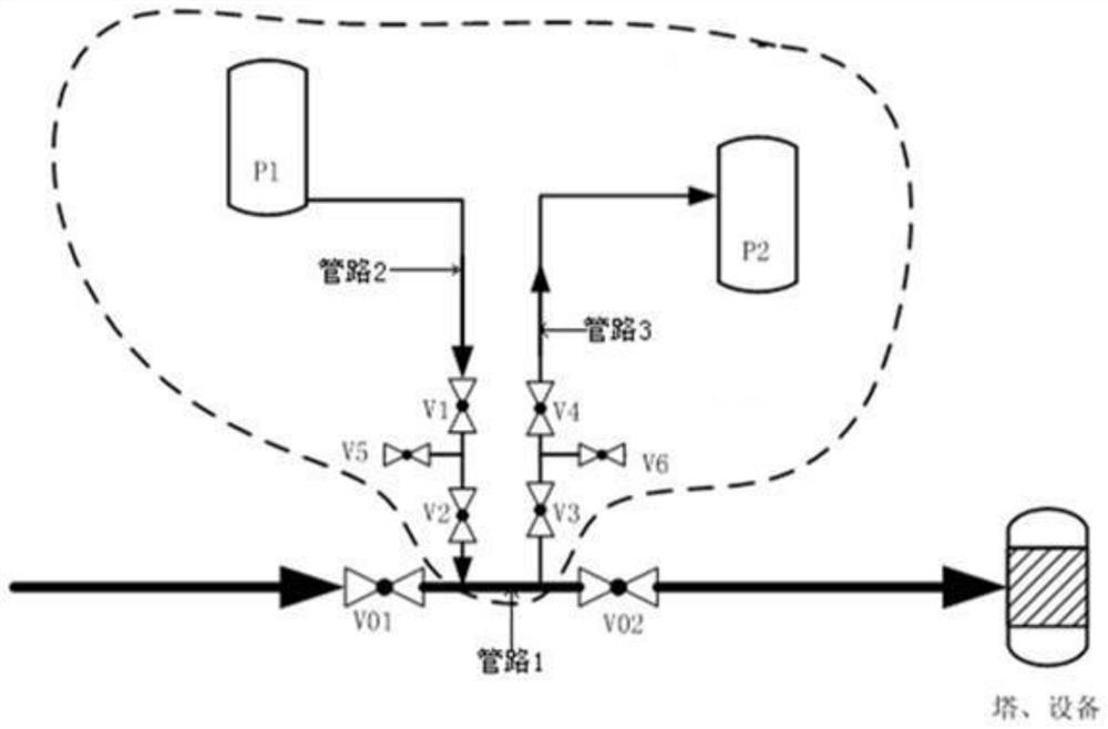
[0027] combine figure 1 The isolation process device and flowchart shown in the figure, valve 1 is VO1, valve 2 is VO2, valve 3 is V1, valve 4 is V2, valve 5 is V5, valve 6 is V3, valve 7 is V4, valve 8 is V6, gas tank 1 is P1, and gas tank 2 is P2.

[0028] Its device is:

[0029] The pipeline between the adjacent valve 1 (VO1) and valve 2 (VO2) that communicates with the equipment is pipeline 1, and pipeline 1 communicates with gas tank 1 (P1) through pipeline 2, and connects with gas tank 1 (P1) through pipeline 3. The gas tank 2 ( P2 ) is in communication; and the junction of pipeline 2 and pipeline 1 is located between the junction of pipeline 3 and pipeline 1 and valve 1 .

[0030] The gas tank 1 (P1) is an inert gas tank; the pressure of the gas in the gas tank 1 is greater than the pressure of the gas in the gas tank 2 .

[0031] The pipeline 2 is provided with a side leakage valve group 1, and the side leakage valve group 1 includes: valve 3 (V1), valve 4 (V2) and ...


PUM


Abstract

The invention relates to an isolation and shielding device and method for internal leakage of a valve. An isolation and shielding device for valve internal leakage, comprising: the pipeline between adjacent valves 1 and 2 is a pipeline 1, the pipeline 1 communicates with the gas tank 1 through the pipeline 2, and the pipeline 3 It communicates with the gas tank 2; the gas tank 1 is an inert gas tank; the pipeline 2 is provided with a side leakage valve group 1, and the side leakage valve group 1 includes: a valve 3, a valve 4 and a valve 5 , the valve 5 is a leak detection valve; the pipeline 3 is provided with a side leakage valve group 2, and the side leakage valve group 2 includes: a valve 6, a valve 7 and a valve 8, and the valve 8 For leak detection valves. The isolation and shielding device and method for valve internal leakage described in the present invention have good shielding effect, high judgment accuracy, low investment cost, save investment in valve replacement, and good environmental protection effect.

Description

technical field [0001] The invention specifically relates to an isolation and shielding device and method for internal leakage of a valve. Background technique [0002] Valves are used to cut off hazardous chemicals and flammable and explosive gases or liquids during pipeline transportation, and the sealing requirements of valves are very high during the cut-off process. Since the valve is subjected to various harsh environments such as temperature, pressure, wear and corrosion during operation, generally the valve cannot achieve 100% leak-free sealing, which will lead to leakage, resulting in run-off, combustion, explosion, etc. Accidents, resulting in the follow-up operations can not be carried out safely. At the same time, the internal leakage and corrosion of the valve will reduce the service life of the valve and damage the valve too quickly, which will affect the economic benefits of the company. The existing method is generally to overhaul the unit, and then replace...

Claims


Application Information

Patent Timeline
Patent Type & Authority Patents(China)
IPC IPC(8): F17D5/02
Inventor 莫银飞
Owner XINJIANG DAQO NEW ENERGY
Learn More