Rolling bearing structure into which wheel speed sensor is embedded

A wheel speed sensor, rolling bearing technology, applied in bearing components, shafts and bearings, bearing assembly and other directions, can solve the problems of poor signal-to-noise ratio, difficult rolling bearing slip rate, high price of vibration sensors and their matching acquisition devices, etc. Ease of use and low cost

Inactive Publication Date: 2019-05-10
XI AN JIAOTONG UNIV +1
View PDF7 Cites 8 Cited by
  • Summary
  • Abstract
  • Description
  • Claims
  • Application Information

AI Technical Summary

Problems solved by technology

The sensors required for vibration measurement are usually arranged on the bearing seat, and the signal is often easily affected by the transmission path and environmental noise, resulting in a poor signal-to-noise ratio, and it is difficult to extract bearing fault features. The above problems are particularly prominent on large, low-speed, heavy-duty bearings
At present, it is difficult to accurately obtain the slip rate of rolling bearings through vibration data analysis. Bearing slipping faults are mostly judged by detecting the degree of slipping burns. Therefore, effective online monitoring methods for slipping faults are needed to monitor the occurrence and development of slipping faults and further study the slipping mechanism. , to propose improvement directions for bearing design and assembly process
In addition, the vibration sensor and its supporting acquisition device are expensive, which is one of the main reasons that limit the promotion of rolling bearing fault diagnosis and condition monitoring technology

Method used


Image

  • Rolling bearing structure into which wheel speed sensor is embedded
  • Rolling bearing structure into which wheel speed sensor is embedded
  • Rolling bearing structure into which wheel speed sensor is embedded

Examples


Embodiment 1

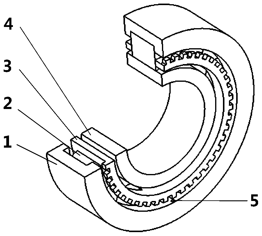
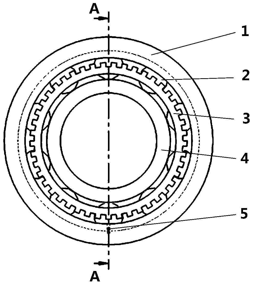
[0023] Example 1, such as Figure 1-Figure 3 As shown, a rolling bearing structure with a built-in wheel speed sensor, including a rolling bearing composed of an outer ring 1, a roller 2, a cage 3 and an inner ring 4, and a sensor body 5 and a cage 3 fixed on the inner hole of the outer ring 1 The ring gear on the top constitutes a magnetoelectric wheel speed sensor, and the non-contact measurement method does not affect the normal operation of the rolling bearing; the ring gear of the magnetoelectric wheel speed sensor and the cage 3 are integrated, and the tooth height of the ring gear is based on the wheel The working range of the speed sensor probe is designed so that the distance between the installed sensor body 5 and the ring gear is within the normal working range of the magnetoelectric wheel speed sensor. When the outer ring 1, roller 2, cage 3, inner ring When a partial fault occurs in components such as 4, the instantaneous speed signal of the cage 3 collected by th...

Embodiment 2

[0025] In Embodiment 2, the fixed form and position of the sensor body 5 are not limited to the form shown in Embodiment 1. Since the sensor body 5 is mainly used to measure the instantaneous rotational speed of the cage 3, as long as it can be fixed on a non-rotating part, The sensor probe can be aligned with the ring gear on the cage 3, for example, the sensor body 5 is fixed on the outer ring 1 in the form of a bracket 6, such as Figure 4-Figure 6 structure shown.

[0026] The tooth direction of the ring gear on the cage 3 can be made radial, such as Figure 1-Figure 3 As shown, it can also be made axial, such as Figure 4-Figure 6 shown.

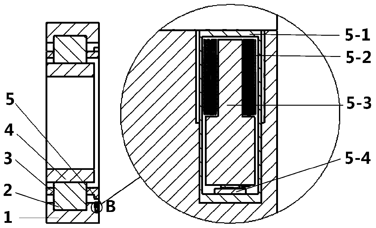
[0027] The working principle of the magnetoelectric wheel speed sensor: when the shaft connected to the inner ring 4 rotates, the cage 3 rotates at its characteristic frequency, and the ring gear on one side continuously cuts the magnetic force lines of the permanent magnet core 5-3 to generate electrical signals , the fault diagnosi...


PUM


Abstract

The invention provides a rolling bearing structure into which a wheel speed sensor is embedded. The rolling bearing structure comprises a rolling bearing formed by connecting an outer ring, a roller,a retainer and an inner ring. The wheel speed sensor is embedded into the rolling bearing, the wheel speed sensor acquires instant rotating speed information of the retainer for fault diagnosis of therolling bearing, and the wheel speed sensor is a magnetoelectric wheel speed sensor or a Hall type wheel speed sensor composed of a sensor body and a gear ring. As in the operating process of the rolling bearing, instant rotating speed signals shown on the retainer comprise rich fault information, transmission and conversion between fault stimulation and the instant rotating speed signals are simpler relative to vibrating signals, the instant rotating speed signals are more sensitive to faults relative to the vibrating signals, and the signal-to-noise ratio is higher. The wheel speed sensor and the rolling bearing are designed into an integrated structure, and the rolling bearing structure is convenient to use and low in cost.

Description

technical field [0001] The invention relates to the technical field of rolling bearing fault diagnosis, in particular to a rolling bearing structure embedded with a wheel speed sensor. Background technique [0002] Rotating machinery is widely used in various fields such as automobiles, aerospace, electric power, and metallurgy. As a key component of rotating machinery, rolling bearings will cause serious consequences and economic losses if they fail. Therefore, rolling bearing fault diagnosis and health management technologies are subject to industry and extensive attention in academia. The fault diagnosis of rolling bearings usually adopts methods such as vibration detection, acoustic emission detection, and oil analysis. The above methods have their own advantages and disadvantages, and the vibration signal analysis method is the most widely used. The sensors required for vibration measurement are usually arranged on the bearing housing, and the signal is often easily af...

Claims


Application Information

Patent Timeline
IPC IPC(8): F16C41/00G01M13/04
Inventor 王琇峰洪银聪区瑞坚
Owner XI AN JIAOTONG UNIV
Why Eureka
Try Eureka