High-efficiency afterburning type compressed air energy storage system

A technology of compressed air energy storage and energy storage system, which is applied in the direction of steam engine device, liquid variable capacity machinery, variable capacity pump components, etc., which can solve the problem of high cost of heat accumulator hardware facilities, high equipment investment cost, and air throttling Problems such as pressure loss, to achieve the effect of easy realization of the combustion process, compact and reasonable structure, and reduced pressure parameters

Inactive Publication Date: 2019-05-10
郭祚刚 +1
View PDF3 Cites 3 Cited by
  • Summary
  • Abstract
  • Description
  • Claims
  • Application Information

AI Technical Summary

Problems solved by technology

[0003] The existing compressed air energy storage technology is divided into two categories, one is the non-supplementary combustion compressed air energy storage technology, in the process of electric energy storage, the electric energy is converted into the pressure energy of compressed air for storage, and the compressor unit generated in this process The exhaust temperature is not high, and the exhaust temperature is usually lower than 150°C, so that the inlet airflow entering the air expander unit can be heated at a lower temperature, which limits the ability of the compressed air to do external work; in addition, it is necessary to configure a large-capacity heat accumulator to To store low-grade compression heat, the cost of heat accumulator hardware facilities is high, which increases the hardware investment cost of compressed air energy storage system
[0004] The second is the post-combustion compressed air energy storage technology. In the process of releasing compressed air to perform work, a burner is installed at the entrance of each stage of the air expander unit. The equipment investment cost is too high. The entrance of the first stage air expander unit The pressure is high, the fuel is directly mixed with high-pressure air under high pressure, and the high-pressure high-temperature flue gas directly enters the first expander unit. This type of burner needs to be burned in a high-pressure environment. Domestic high-pressure combustion The burner technology is immature, and a burner is installed at the inlet of each air expander, resulting in excessive natural gas consumption, resulting in excessively high exhaust gas temperature of the last air expander, and reducing the efficiency of the entire compressed air energy storage system
[0005] In addition, the air required for the combustion of the pressurized burner in the existing post-combustion compressed air energy storage system directly uses the compressed air stored in the gas storage space, and the high-pressure air in the gas storage space is throttled down to the pressure required by the burner. The depressurized air is supplied to the burner for combustion. However, this method has a large air throttling pressure loss. At the same time, the temperature of the compressed air in the air storage space is low, that is, the temperature of the air supplied to the burner is low, which increases the temperature of the burner. fuel consumption

Method used


Image

  • High-efficiency afterburning type compressed air energy storage system
  • High-efficiency afterburning type compressed air energy storage system
  • High-efficiency afterburning type compressed air energy storage system

Examples


Embodiment 1

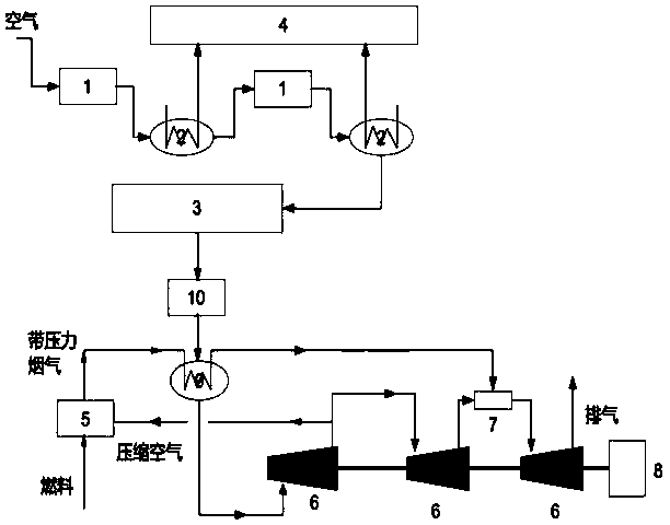
[0037] In this embodiment, the energy is stored during the low electricity price period at night, and the electric energy is released during the peak electricity price period during the day. see figure 1 , is the high-efficiency post-combustion compressed air energy storage system described in the present invention. The electric energy energy storage process is carried out at night when the electricity price is low, and the air compression unit 1 is driven by the cheap electric energy during the low electricity price to prepare high-pressure compressed air and store it in the gas storage. In space 3, the wave valley electric energy is transformed into the pressure energy of compressed air.

[0038] The trough electric energy drives multiple air compression units 1 to work. After the air is sucked into the air compression unit 1, the pressure increases, and the temperature of the air discharged from the air compression unit 1 increases. The heat carried by the compressed air is...

Embodiment 2

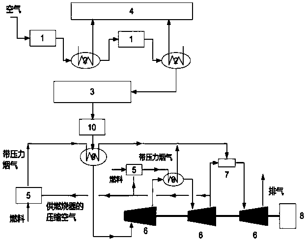
[0043] In this embodiment, the energy is stored during the low electricity price period at night, and the electric energy is released during the peak electricity price period during the day. The difference from Embodiment 1, such as figure 2 As shown, in the technical solution provided by Embodiment 2 of the present invention, two sets of burners 5 and two sets of second heat exchangers 9 are used, and the second heat exchanger 9 of the second set is arranged At the entrance of the second expander unit 6, the second burner 5 is arranged at the entrance of the second second heat exchanger 9, and the pressurized flue gas produced by the burner 5 flows through the two second heat exchangers respectively. The heaters 9 merge afterward. After the confluence, the two paths of pressurized flue gas pass through the gas mixing device 7, and are mixed with the pressurized flue gas discharged from the second expander unit 6 to form the same uniform working air flow, which enters the thi...

Embodiment 3

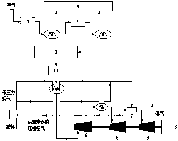
[0046] In this embodiment, the energy is stored during the low electricity price period at night, and the electric energy is released during the peak electricity price period during the day. like image 3 As shown, the difference compared with the second embodiment, a burner 5 is adopted in the third embodiment provided by the present invention, and the pressurized flue gas produced by the burner 5 can be divided into multiple streams and flow to different second converters respectively. Heater 9, multiple strands of pressurized flue gas are combined after the compressed air flow in the second heat exchanger 9 is heated, and the combined two-way flue gas passes through the gas mixing device 7 and is compressed with the compressed air discharged from the second expander unit 6. The air flow is mixed to form the same uniform work flow, which enters the third expander unit 6 to do work, output the shaft work, and discharge the exhaust air. The compressed air used by the combusto...


PUM


Abstract

The invention discloses a high-efficiency afterburning type compressed air energy storage system. The high-efficiency afterburning type compressed air energy storage system comprises an electric energy storage system and an electric energy release system, wherein the electric energy storage system comprises a plurality of air compression units, a first heat exchanger, an air storage space and an energy storage system heat storage tank, and the electric energy release system comprises a plurality of combustors, a combustor air supply system, a plurality of second heat exchangers, a plurality ofexpansion machine units, an energy storage system waste-heat recycling heat exchanger, a gas mixing device and a generator. According to the high-efficiency afterburning type compressed air energy storage system, the compressed air required by the combustor is the pressured exhaust gas of an expansion machine unit, the pressured exhaust gas of the expansion machine unit is subjected to partial work for recycling part of energy, and the fuel consumption is reduced. The gas mixing device mixes pressured flue gas with the pressured exhaust gas of the expansion machine unit, the mixed gas entersthe expansion machine unit to work for recycling flue gas heat and pressure energy, waste heat is reused by the energy storage system, and the heat of bearing lubricating oil of devices such as the air compression units, the expansion machine unit and the engine are recycled, so that the efficiency of the energy storage system is greatly improved.

Description

technical field [0001] The invention relates to the field of electric energy storage, and is specifically used for large-scale energy storage of power grid electric energy to realize peak-shaving and valley-filling of power grid loads, and can also be used for high-efficiency supplementary combustion compressed air storage for new energy electric energy grid connection and large-scale storage of electric energy. energy system. Background technique [0002] Compressed air energy storage technology is a large-scale physical energy storage technology. When the power grid is in a low load period, the cheap electric energy during the valley period is used to drive the air compressor unit to do work, and the cheap low-valley electric energy is converted into the pressure energy of compressed air for storage. When the power grid is at the peak of power consumption, the high-pressure compressed air in the storage tank is released. After passing through the heat exchanger or burner t...

Claims


Application Information

Patent Timeline
Patent Type & Authority Applications(China)
IPC IPC(8): F04B41/02F04B41/06F04B39/06F01K23/12F01K27/00
CPCY02E60/16
Inventor 郭祚刚翟晓慧
Owner 郭祚刚
Why Eureka
Try Eureka