Pallet truck and auxiliary wheel assembly

A technology for auxiliary wheels and assemblies, applied to vehicle components, elastic suspensions, lifting devices, etc., can solve the problem that the load distribution between driving wheels and auxiliary wheels cannot be adjusted as required, the installation surface is difficult to meet the precise requirements, and the load distribution adjustment cannot be completed And other issues

Pending Publication Date: 2019-05-10
HANGCHA GRP
View PDF0 Cites 0 Cited by
  • Summary
  • Abstract
  • Description
  • Claims
  • Application Information

AI Technical Summary

Problems solved by technology

However, the amount of force on the auxiliary wheel 03 is related to the compression of the spring 04, and the compression of the spring 04 is directly determined by the height difference between the driving wheel 01 and the auxiliary wheel 03, and this height difference depends on the height difference between the driving wheel 01 and the auxiliary wheel 03. The respective installation positions, the driving wheel 01 and the auxiliary wheel 03 are all installed on the frame. Due to manufacturing errors, the installation surface of the driving wheel 01 and the auxiliary wheel 03 is difficult to meet the precise requirements, which eventually leads to the gap between the driving wheel 01 and the auxiliary wheel 03. The load distribution is not ideal; in addition, the theoretically designed load distribution of the driving wheel 01 and the auxiliary wheel 03 cannot be applied to all working conditions, and the above-mentioned structure of the driving wheel 01 and the auxiliary wheel 03 cannot be completed once it is installed Adjustments to load distribution
[0004] Therefore, how to avoid the load distribution of the driving wheel and the auxiliary wheel from being unable to adjust as required is a technical problem to be solved by those skilled in the art

Method used


Image

  • Pallet truck and auxiliary wheel assembly
  • Pallet truck and auxiliary wheel assembly
  • Pallet truck and auxiliary wheel assembly

Examples


Embodiment Construction

[0027] The technical solutions in the embodiments of the present invention will be clearly and completely described below with reference to the accompanying drawings in the embodiments of the present invention. Obviously, the described embodiments are only a part of the embodiments of the present invention, but not all of the embodiments. Based on the embodiments of the present invention, all other embodiments obtained by those of ordinary skill in the art without creative efforts shall fall within the protection scope of the present invention.

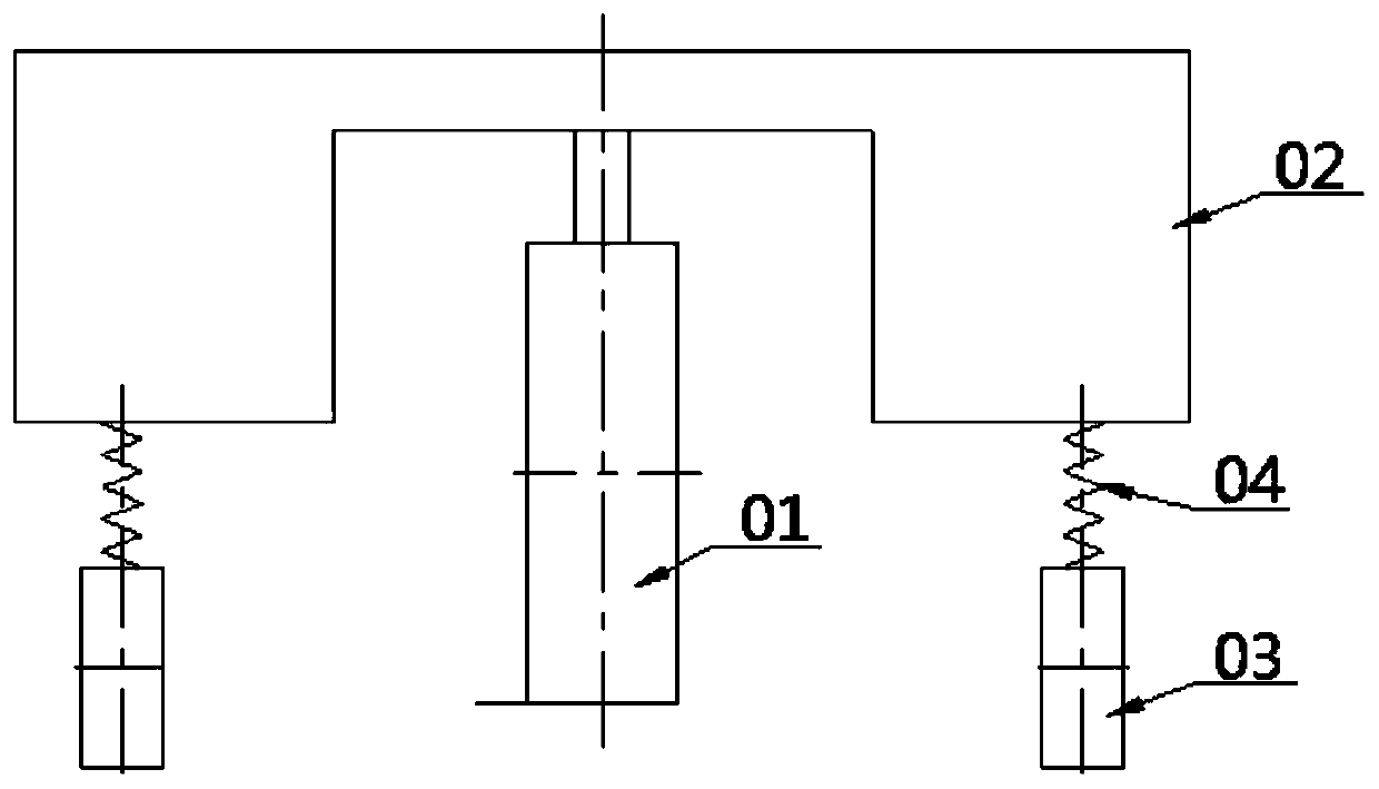
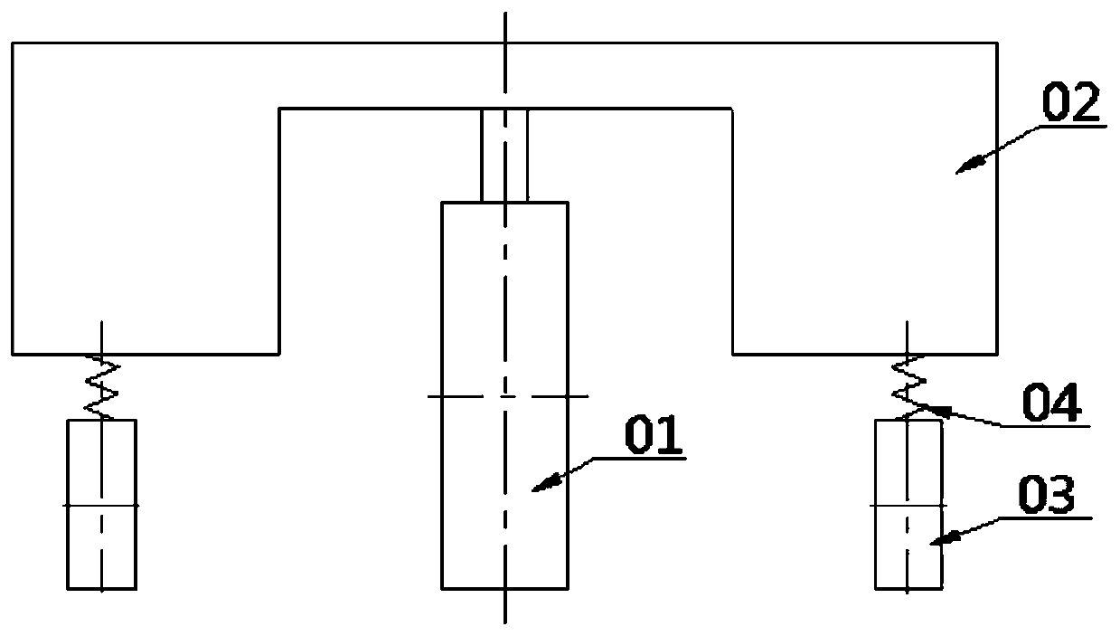
[0028] The core of the present invention is to provide an auxiliary wheel assembly, which can accurately adjust the load on the auxiliary wheel to increase or decrease according to the requirements, so as to redistribute the load of the driving wheel and the auxiliary wheel, At the same time, waste caused by manufacturing errors of components can be avoided, thereby saving costs. Another core of the present invention is to provide a p...


PUM


Abstract

The invention discloses an auxiliary wheel assembly. The auxiliary wheel assembly comprises an upper bracket, a lower bracket and a spring, wherein the lower bracket is rotationally connected with theupper bracket; the spring abuts against the lower bracket in a contacting manner and is used for providing an elastic force; the auxiliary wheel assembly further comprises an ejection rod part and ananti-loosening part, wherein the ejection rod part is connected with the upper bracket and abuts against the spring in a contacting manner to adjust the elastic force of the spring; and the anti-loosening part closely fits the end surface of the external side of the upper bracket to prevent the ejection rod part from being loosened. The invention further discloses a pallet truck including the auxiliary wheel assembly. The auxiliary wheel assembly can accurately adjust load borne on an auxiliary wheel according to a demand so that an influence caused by a manufacturing error in the productionand assembling process can be reduced; and moreover, resources can be saved, and the production cost can be reduced; and meanwhile, the elastically adjustable auxiliary wheel assembly can be applied to more models.

Description

technical field [0001] The invention relates to the technical field of forklift assembly, in particular to an auxiliary wheel assembly. The invention also relates to a pallet truck with the auxiliary wheel assembly. Background technique [0002] A pallet truck is a general term for a type of forklift, including pallet jacks and pallet stackers. [0003] Currently, if figure 1 and figure 2 As shown, the drive system of the pallet truck (including the driving wheel 01) is rigidly connected with the frame 02, while the auxiliary wheels 03 on both sides of the driving wheel 01 are elastically connected with the frame 02, that is, the auxiliary wheels 03 are elastic ( Usually through the spring 04), the height difference between the auxiliary wheel 03 and the driving wheel 01 is set in the design, so that when the vehicle is on a level road, the spring 04 of the auxiliary wheel 03 has a certain amount of pre-compression, and the elasticity of the spring 04 It acts on the aux...

Claims


Application Information

Patent Timeline
IPC IPC(8): B60G11/16B60G3/00B66F9/075
Inventor 姜宗平匡灏尚乐孙健琛王建麒阮镜宣杨亮罗星
Owner HANGCHA GRP
Why Eureka
Try Eureka