Ramjet generator for suction and exhaustion pipes

A generator and exhaust pipe technology, applied in exhaust devices, machines/engines, combustion air/combustion-air treatment, etc., can solve the problem of difficulty in increasing air supply, air flow rate and fuel mixing ratio, and no rapid exhaust gas discharge. and other problems, to achieve the effect of improving intake and exhaust efficiency, simple installation and disassembly

Inactive Publication Date: 2019-05-07
李东奎
View PDF9 Cites 0 Cited by
  • Summary
  • Abstract
  • Description
  • Claims
  • Application Information

AI Technical Summary

Problems solved by technology

In addition, the incoming air is only accelerated at a predetermined section of the intake pipe when passing through the turbine generator with multiple blades inside the cylindrical pipe, and the distance the air flows will be limited by the friction on the inner wall of the intake pipe, so it is still difficult to increase the air supply volume, air flow rate and optimized fuel mixture ratio
[0011] Also, there is no technology for quickly exhausting exhaust gases, and different types and sizes of internal combustion engines require specific vortex generators

Method used


Image

  • Ramjet generator for suction and exhaustion pipes
  • Ramjet generator for suction and exhaustion pipes
  • Ramjet generator for suction and exhaustion pipes

Examples


Embodiment Construction

[0047] The ram generator of the present invention will be described in detail below in conjunction with the accompanying drawings.

[0048] In the following description of the present invention, a detailed description of well-known functions or constructions related to the present invention will not be provided so as not to obscure the description of the present invention with unnecessary detail.

[0049] The terms described below are set in consideration of the functions of the present invention and may be changed according to the manufacturer's intention or use, so the definitions should be based on the entire specification.

[0050] The invention is logically described below with reference to the accompanying drawings.

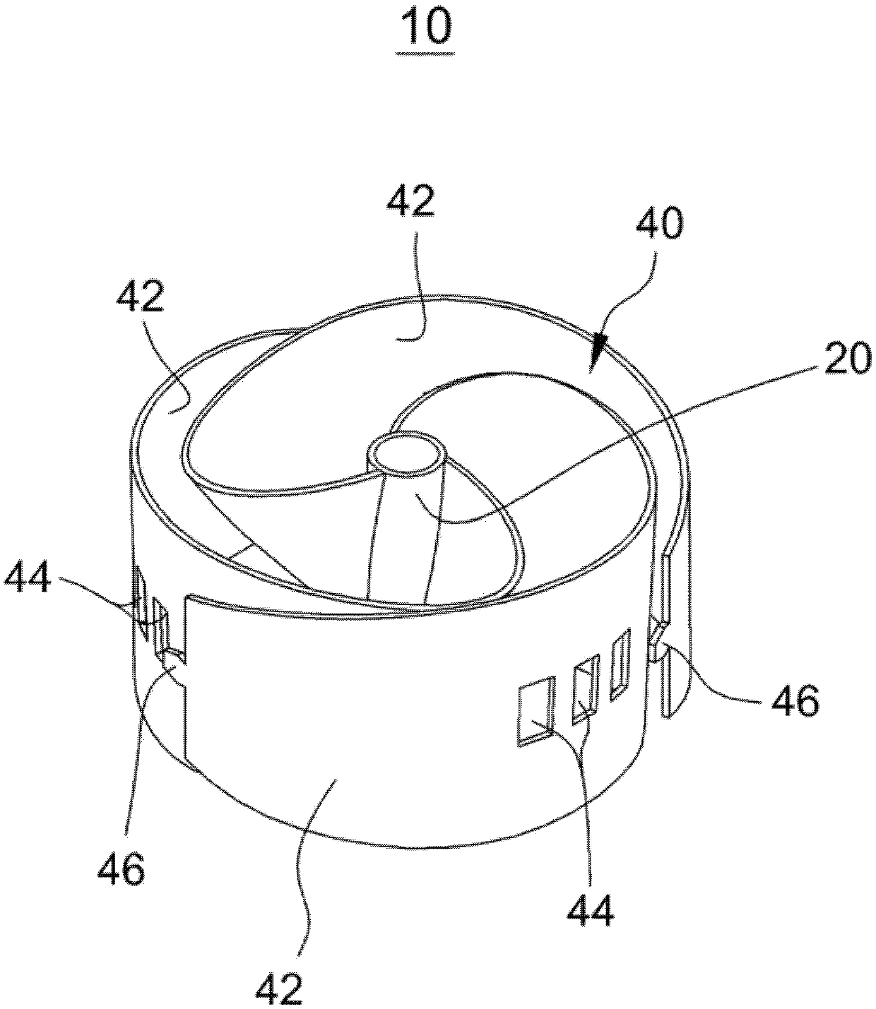
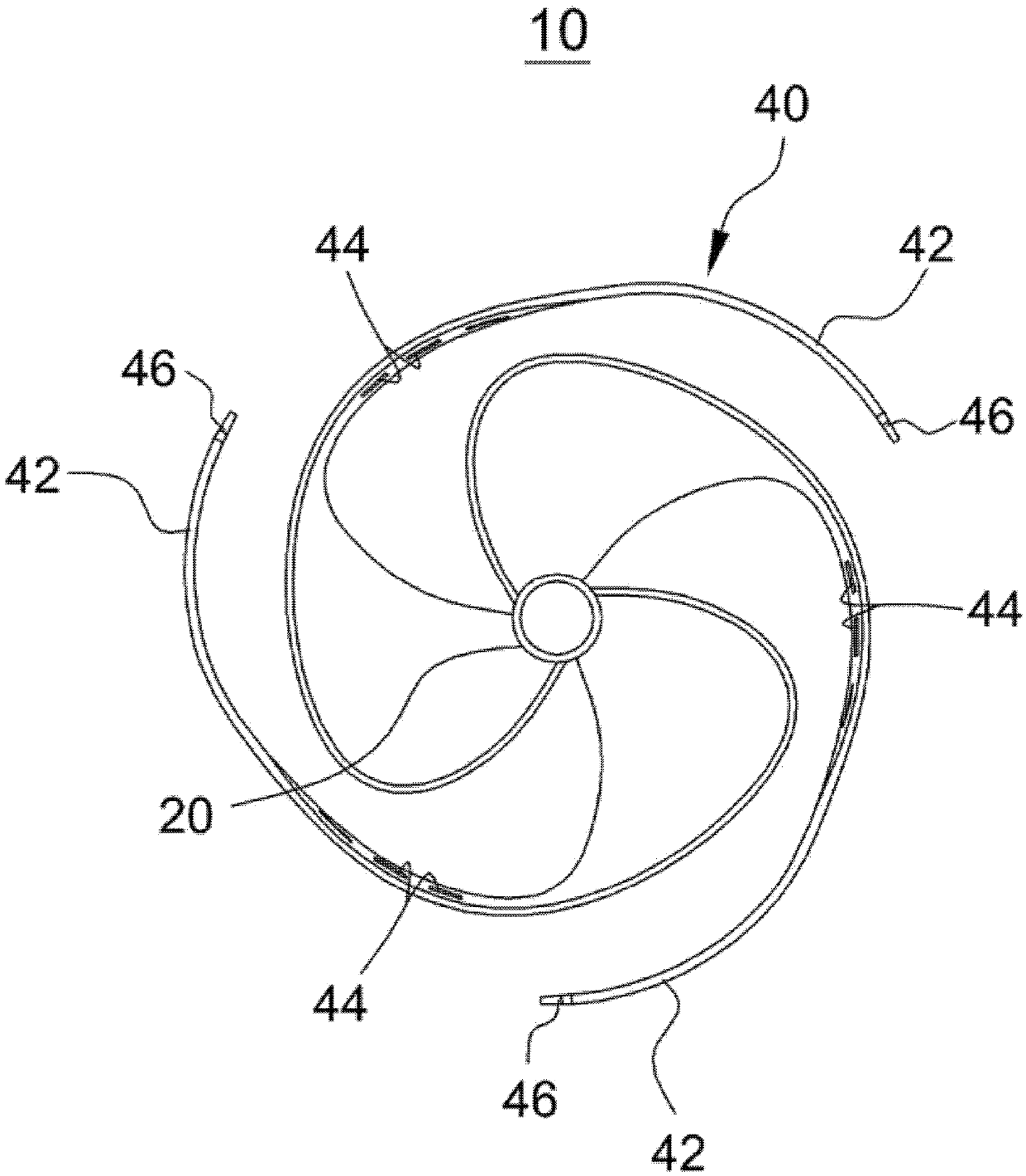
[0051] figure 1 is a perspective view of a punch generator according to an exemplary embodiment of the present disclosure, figure 2 Yes figure 1 The front view of the blade shown before assembly, image 3 Yes figure 1 A front view of the blade shown i...


PUM


Abstract

Disclosed is a ramjet generator for suction and exhaustion pipes. The ramjet generator comprises: a central jet portion having a preset length and provided at the inside of suction and exhaustion pipes, and a swirl generating portion having two or more blades, wherein one side of each of the blades is connected to the central jet portion and extends outward from the inside in a preset area; and the blades have elastic force and are in contact with the interior surface of the suction and exhaustion pipes of the internal engine, and have a shape of the external circumferential surface of the swirl generating portion so as to correspond to a shape of the internal surface of the suction and exhaustion pipes of the internal combustion engine. The ramjet generator of the present invention can generate swirl by ramjet increasing a flow velocity of the air, thereby capable of improving air velocity in the suction and exhaustion pipes connected to the engine and an air filter of the internal combustion engine so as to improve the suction and exhaustion efficiency of the internal combustion engine.

Description

[0001] Cross References to Related Applications [0002] This application claims priority from Korean Patent Application No. 10-2017-0142735 filed on October 30, 2017, the entire contents of which are hereby incorporated by reference for all purposes. technical field [0003] The invention relates to stamping for intake / exhaust pipes The field of generators, more particularly, relates to a ram generator for an intake / exhaust pipe capable of improving the connection between an engine and an air filter of an internal combustion engine by utilizing the vortex generated by a vortex generator. The air flow rate in the intake / exhaust pipe of the internal combustion engine is improved to improve the intake and exhaust efficiency of the internal combustion engine, and regardless of the type and size of the internal combustion engine, the ram generator is in close contact with the inner side of the intake / exhaust pipe, Background technique [0004] The internal combustion engine of...

Claims


Application Information

Patent Timeline
Patent Type & Authority Applications(China)
IPC IPC(8): F02B31/04F01N13/08F02M35/104
CPCF01N3/2892F01N13/007F01N13/08F02B31/04Y02T10/12F02B27/06F01N1/086
Inventor 李东奎
Owner 李东奎
Why Eureka
Try Eureka