Bending modeling die

A technology for molds and bending plates, applied in forming tools, manufacturing tools, metal processing equipment, etc., can solve problems such as increasing difficulty in equipment use, affecting equipment work efficiency, and unsatisfactory forming effects, and improving practical reliability and safety. , the operation process is convenient, the equipment structure is simple

Active Publication Date: 2019-05-07
青岛顺泰钢结构工程有限公司
View PDF5 Cites 1 Cited by
  • Summary
  • Abstract
  • Description
  • Claims
  • Application Information

AI Technical Summary

Problems solved by technology

[0002] The bending operation needs to be realized by bending dies. In the existing technology, the bending process of the cuboid often requires multiple bending of the punched parts to form a qualified product. In this process, if the cuboid When the size changes, it is necessary to adjust the relevant instrument parameters of the bending equipment, and a large number of calculations are required, which makes the use of the equipment more difficult, and in the working process of the traditional bending equipment, the bending accuracy of the smaller size is lower , and the forming effect is not ideal. The fundamental reason is that during the bending process, due to the fixed length of the upper mold, smaller workpieces cannot be pressed and punched better. The above shortcomings affect the working efficiency of the equipment.

Method used


Image

  • Bending modeling die
  • Bending modeling die
  • Bending modeling die

Examples


Embodiment Construction

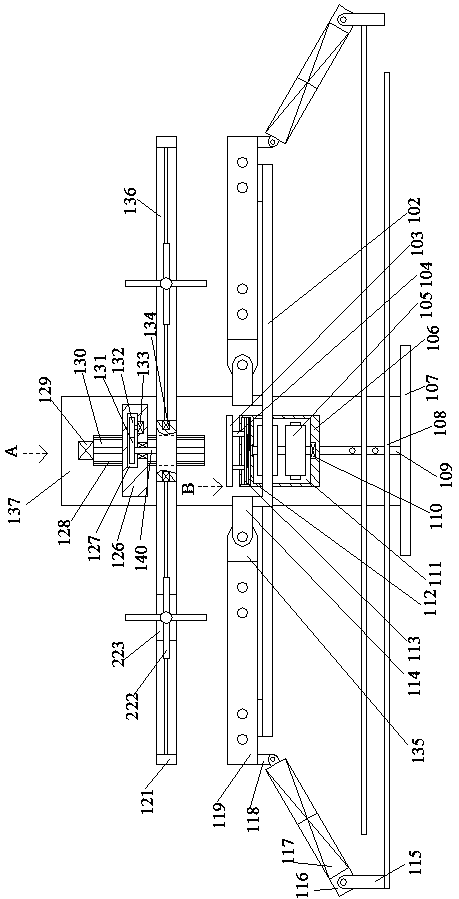
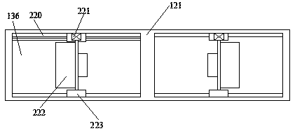
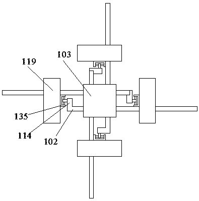
[0022] like Figure 1-Figure 4 As shown, the present invention is described in detail. For the convenience of description, the orientations mentioned below are now stipulated as follows: figure 1 The up, down, left, right, front and back directions of the projection relationship are consistent. A bending molding die of the present invention includes a bottom plate 107. A pressing device for pressing the workpiece is arranged on the front side of the bottom plate 107. The upper end surface of the bottom plate 107 is fixed with a A vertical box 137, the vertical box 137 is connected with a power chamber 130, and the power chamber 130 is provided with a driving device that drives the pressing device to move up and down, and the upper end surface of the bottom plate 107 is fixedly provided with an adjustment distance between each other, so that A bending device for efficiently bending a workpiece, thereby realizing efficient blanking of the workpiece by using the above-mentioned d...


PUM


Abstract

The invention discloses a bending modeling die which comprises a bottom plate. A pressing device used for pressing a workpiece is arranged on the front side of the bottom plate. A vertical box is fixedly arranged on the upper end face of the bottom plate. A power cavity is formed in the vertical box in a communicating manner. A drive device for driving the pressing device to move up and down is arranged in the power cavity. A bending device for adjusting the mutual distance and bending the workpiece efficiently is fixedly arranged on the upper end face of the bottom plate. The bending modelingdie is simple in structure, the manner of forming and bending the workpiece at a time is adopted, when related parameters are adjusted, a corresponding motor only needs to be driven to drive relatedstructures to move to the designated position, the operation process is more convenient, in the bending process, only one set of equipment is adopted for carrying out bending machining, different diesdo not need to be replaced, meanwhile, the equipment can machine the workpieces of different sizes according to adjustment of the related structures in the equipment, on one hand, the technology range of the equipment is enlarged, and on the other hand, the practical reliability and safety of the equipment are improved.

Description

technical field [0001] The invention relates to the technical field of bending molding dies, in particular to a bending molding die. Background technique [0002] The bending operation needs to be realized by bending dies. In the existing technology, the bending process of the cuboid often requires multiple bending of the punched parts to form a qualified product. In this process, if the cuboid When the size changes, it is necessary to adjust the relevant instrument parameters of the bending equipment, and a large number of calculations are required, which makes the use of the equipment more difficult, and in the working process of the traditional bending equipment, the bending accuracy of the smaller size is lower , and the forming effect is not ideal. The fundamental reason is that the length of the upper mold is fixed during the bending process, so that the workpiece with a smaller size cannot be better compressed and punched. The above shortcomings affect the working eff...

Claims


Application Information

Patent Timeline
IPC IPC(8): B21D37/10B21D43/00
Inventor 王宏斌
Owner 青岛顺泰钢结构工程有限公司
Why Eureka
Try Eureka