
Hydraulic breaking hammer

A hydraulic breaker and liquid technology, applied in fluid pressure converters, fluid pressure actuators, cylinders, etc., can solve the problems of increasing user costs, labor and time, and breakage, so as to improve processing efficiency and reduce use costs , the effect of simple overall structure

Active Publication Date: 2019-05-03
SHANDONG TIANRUI HEAVY IND CO LTD
View PDF6 Cites 0 Cited by
  • Summary
  • Abstract
  • Description
  • Claims
  • Application Information

AI Technical Summary

Problems solved by technology

[0004] The hydraulic breaker of the prior art has the following deficiencies: First, the distribution valve and the piston are arranged in parallel, whether it is a built-in distribution valve or an external
This will cause serious waste and increase the user's cost
[0005] The second is that there are a lot of holes in the cylinder of the breaker, and there are many machining processes.
The grinding process is very complicated. Since the hole for installing the piston and the hole for installing the distribution valve are arranged in parallel, the grinding process of the two holes is an eccentric processing mode, which is labor-intensive and time-consuming, and the processing cost is high.
[0006] The third is that the structure of the distribution valve is complex, and the machining accuracy is very high.
In the process of use, there are often strains and breakages

Method used


Image

  • Hydraulic breaking hammer
  • Hydraulic breaking hammer
  • Hydraulic breaking hammer

Examples


Embodiment Construction

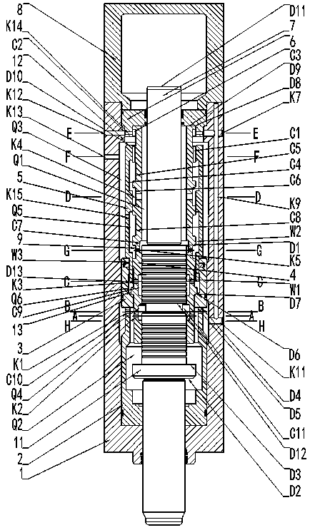
[0055] Examples such as Figure 2-17 As shown, a hydraulic breaker includes a middle cylinder 1 with a cavity inside, a reciprocating piston 7 is arranged inside the middle cylinder 1, and a hydraulic cycle for driving the movement of the piston 7 is arranged between the middle cylinder 1 and the piston 7 System, one end of the middle cylinder 1 is provided with a gas drive mechanism that assists the hydraulic circulation system to drive the piston 7 to move.

[0056] The hydraulic circulation system includes an inner cylinder 4 with a cylindrical structure, and the inner cylinder 4 is coaxially assembled on the piston 7 near one end.

[0057] The outer circumference of the inner cylinder 4 is sequentially provided with a ring-shaped inner cylinder first annular groove C3, an inner cylinder second annular groove C5, an inner cylinder third annular groove C6, and an inner cylinder from one end of the inner cylinder 4 to the other end. The fourth annular groove C8;

[0058] Th...


PUM


Abstract

The invention discloses a hydraulic breaking hammer. The hammer comprises a cylinder sleeve, a piston capable of doing reciprocated motion is arranged in the cylinder sleeve, a hydraulic circular system used for driving the piston to move is arranged between the cylinder sleeve and the piston, the cylinder sleeve is provided with a gas driving mechanism for assisting the hydraulic circular systemin driving the piston to move, the design thinking of a traditional hydraulic breaking hammer can be broken through, structure innovation of parallel arrangement of the piston and a flow distributionvalve is achieved, and the phenomenon that when the stop position of the piston or the flow distribution valve is not proper, the breaking hammer is not started is avoided; the hammer is simple in whole structure, materials can be saved by more than 30%, machining is easy, cost is reduced, and the machining efficiency is improved by more than 40%. When pulling appears, a certain small part in thehammer is replaced, the cylinder sleeve does not need to be replaced, the use cost of a user is reduced, through technical application and popularization, the research and development thinking of thebreaking hammer industry is changed, and the national breaking hammer industrial technological innovation steps onto the new step.

Description

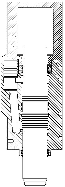
technical field [0001] The invention relates to a crushing device, in particular to a hydraulic breaker used in mining, metallurgy, railways, highways, municipal gardens, buildings, ships, etc., and belongs to the technical field of engineering machinery. Background technique [0002] The hydraulic breaker is referred to as "breaker" or "breaker", which is installed on excavators and loaders where buckets or buckets are installed, and is used to break stones, rocks, etc., such as figure 1 shown. [0003] The working principle of the hydraulic breaker is: powered by the output pressure oil of the hydraulic pump of the excavator and loader, the reciprocating motion of the piston is controlled through the distribution valve. During the stroke, the rear cavity of the middle cylinder of the hammer is filled with high-pressure hydraulic oil, and the piston is impacted by the compressed nitrogen in the upper cylinder and the high-pressure oil to smash the rock; The piston moves b...

Claims


Application Information

Patent Timeline
IPC IPC(8): F15B15/14F15B15/20F15B3/00F16J10/02E02F5/30
Inventor 李永胜王维林杨琦王秋景王虹李伟张婕妤郑伟王磊
Owner SHANDONG TIANRUI HEAVY IND CO LTD
Learn More