


Quick Research
Generate reliable direction feasibility study reports for your R&D in just a few steps.

Technical Q&A
Discover and master advanced knowledge NOW. Basics, ideas, possibilities, all at once.

Find Solutions
As an expert in R&D theories, this can generate solutions to your technical problems instantly.

Evaluate Feasibility
Analyze your overall solution with one click, know your potential R&D risks in advance.

Monitor Landscape
Get weekly tech updates, stay abreast of the latest tech innovations and key insights.
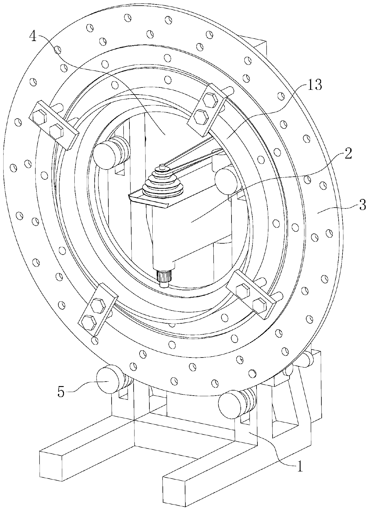
Drilling device for steam turbine shroud
A technology of steam turbine shroud and drilling device, which is applied in positioning device, boring/drilling, drilling/drilling equipment, etc., can solve the problems of large production investment, affecting the economic benefits of enterprises, and small processing volume. , to achieve the effect of improving the economic benefit of the enterprise, reducing the production cost and ensuring the accuracy
- Summary
- Abstract
- Description
- Claims
- Application Information
AI Technical Summary
Problems solved by technology
Method used
Image

Examples
Embodiment 2
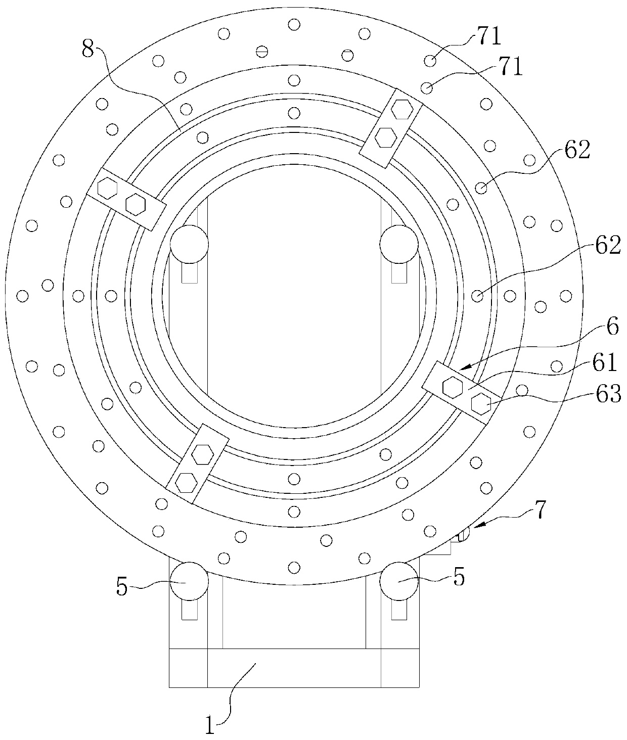
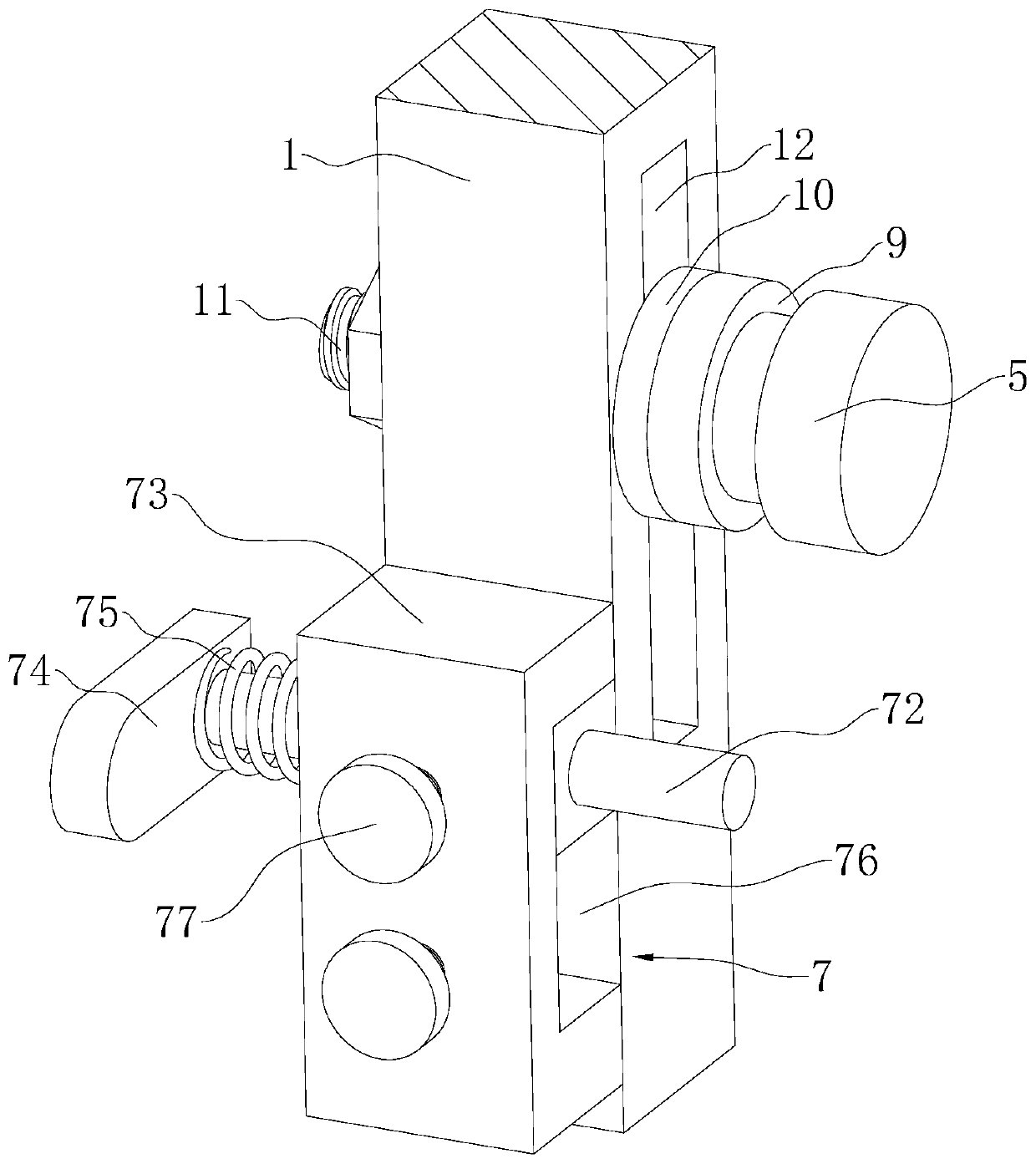
[0037] Embodiment 2: refer to figure 2 and 3 , the difference from Embodiment 1 is that the above-mentioned positioning holes 71 are arranged in two groups along the radial direction of the positioning plate 3, and the spacing between the adjacent positioning holes 71 of the same group is different; the above-mentioned frame 1 is provided with a mounting seat 73 drive slots 76 that move up and down, frame 1 is screwed with two positioning bolts 77 identical with drive slots 76 along its height direction; One side of mounting base 73 offers the installation hole that is equated with the diameter of positioning bolts 77; When the seat 73 slides along the drive groove 76, the positioning holes 71 communicate with the two positioning bolts 77 respectively, and the positioning bolts 77 are inserted into the mounting holes to limit the position of the mounting seat 73, and when the positioning bolts 77 are inserted into the mounting holes , the inserting rod 72 is fitted with the ...
Embodiment 3
[0039] Embodiment 3: refer to figure 2 and 4 , and the difference from Embodiment 2 is that the above-mentioned positioning holes 71 are arranged in two groups along the radial direction of the positioning disk 3 , and the distances between adjacent positioning holes 71 of the same group are different. The above-mentioned insertion rod 72 and the mounting seat 73 are provided with two sets corresponding to two sets of positioning holes 71 and arranged along the height direction of the frame 1, and the mounting seat 73 is fixed on the frame 1; wherein, the handle 74 passes through a bearing (not shown in the figure) Rotately connected with the insertion rod 72, the two ends of the tension spring 75 are respectively fixed with the mounting seat 73 and the bearing; the side of the frame 1 relative to the positioning plate 3 is fixed with a positioning rod 78, and the positioning rod 78 is between the two insertion rods 72; When the handle 74 is overturned, the handle 74 abuts a...
PUM
 Abstract
Description
Claims
Application Information
 - R&D Engineer
- R&D Manager
- IP Professional
- Industry Leading Data Capabilities
- Powerful AI technology
- Patent DNA Extraction
Browse by: Latest US Patents, China's latest patents, Technical Efficacy Thesaurus, Application Domain, Technology Topic, Popular Technical Reports.
© 2024 PatSnap. All rights reserved.Legal|Privacy policy|Modern Slavery Act Transparency Statement|Sitemap|About US| Contact US: help@patsnap.com