Eureka AIR delivers breakthrough ideas for toughest innovation challenges, trusted by R&D personnel around the world.

Dispensing head for LED solid crystal and dispensing method of LED solid crystal

A technology of dispensing head and die-bonding, applied in the field of semiconductor lighting, can solve the problems of short-circuit welding of LED chips, poor die-bonding, and LED chip pressing offset, etc., to achieve high reliability, good efficiency, and avoid chip overflow. Effect

Active Publication Date: 2019-05-03
广东晶锐半导体有限公司
View PDF8 Cites 1 Cited by
  • Summary
  • Abstract
  • Description
  • Claims
  • Application Information

AI Technical Summary

Problems solved by technology

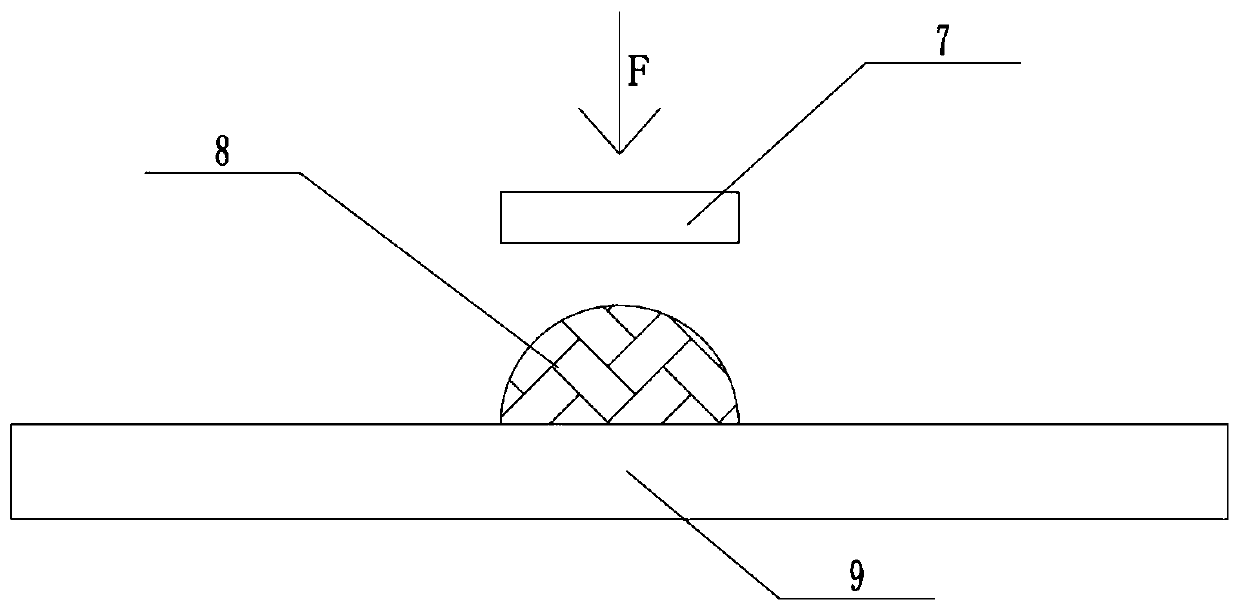
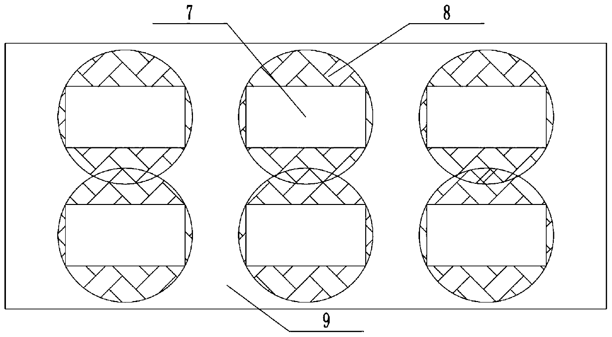
[0003] The traditional die-bonding glue coating method is to point the die-bonding glue on the substrate in the shape of a ball or a drop through the automatic dispensing head, and then cover the LED on the substrate and squeeze the die-bonding glue to apply a Downforce F, and then flatten the spherical or drop-shaped die-bonding glue (such as figure 1 ), due to the spherical characteristics and the surface tension of the liquid, the die-bonding adhesive will be flattened into a cylindrical adhesive layer under the pressure F. Usually, the circular area of ​​the cylinder will be larger than the size of the chip. Due to the conventional The LED chips are all square structures, so more die-bonding glue will overflow the chip, and the setting will cause the conductive glue to overflow the pad or the insulating glue to cover the pad, which will cause a short circuit or poor soldering of the LED chip. When the situation occurs, especially when the COB light source is finely wired, it may overflow to other pads and cause a short circuit (such as figure 2 )
The current conventional method is to reduce the amount of glue dispensed, but if the amount of glue is too small, that is, if the amount of glue is too small, the LED chip will not be firmly attached to the substrate. Therefore, the control of glue amount has become a major problem in the industry. one
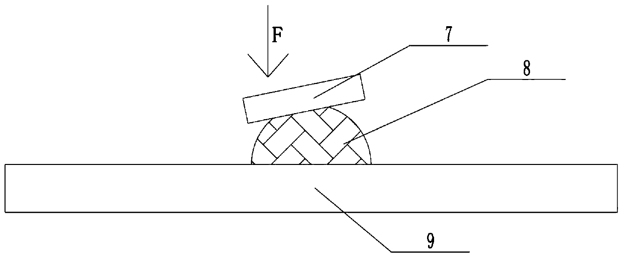
[0004] In addition, since the top of the spherical or drop-shaped die-bonding adhesive is generally arc-shaped, after the LED chip is placed on the die-bonding adhesive, if the pressure F provided is not in the middle of the LED chip and the die-bonding adhesive, it may cause The pressing down of the LED chip deviates, and at the same time, the uneven die-bonding adhesive layer at the bottom of the LED chip causes the LED chip to warp (such as image 3 ), resulting in poor die bonding, which is not conducive to the light emission, heat dissipation and reliability of the chip

Method used


Image

  • Dispensing head for LED solid crystal and dispensing method of LED solid crystal
  • Dispensing head for LED solid crystal and dispensing method of LED solid crystal
  • Dispensing head for LED solid crystal and dispensing method of LED solid crystal

Examples


Embodiment Construction

[0038] The present invention will be described in detail below in conjunction with the accompanying drawings.

[0039] A kind of dispensing head for LED solid crystal of the embodiment of the present invention is as Figure 4-5 As shown, it includes a pneumatic mechanism 1 and a glue supply mechanism. The glue supply mechanism is located below the pneumatic mechanism 1. The pneumatic mechanism 1 drives the glue supply mechanism. The glue supply mechanism includes two mirror-imaged glue supply mechanisms. structure, the glue supply structure is fixed under the pneumatic mechanism 1, the glue supply structure includes a connecting rod 2, a glue supply hose 3 and an extruder, and the glue supply hose 3 is fixed on the Below the pneumatic mechanism 1, the shape of the rubber supply hose 3 is L-like, the extruder is arranged at the lower end of the rubber supply hose 3, and the upper end of the rubber supply hose 3 is connected to the glue supply device, Two mirrored extruders are...


PUM


Abstract

The invention discloses a dispensing head for LED solid crystal. The dispensing head for LED solid crystal comprises a pneumatic mechanism and a glue supply mechanism, the glue supply mechanism is located below the pneumatic mechanism, the pneumatic mechanism drives the glue supply mechanism, the glue supply mechanism comprises two glue supply structures in a mirror image mode, the glue supply structures are fixed to the lower part of the pneumatic mechanism, and the glue supply structures comprise connecting rods, glue supply pipes and extruders. The glue supply pipes are fixed to the lower part of the pneumatic mechanism through the connecting rods, the shape of the glue supply pipes is an L shape, the extruders are arranged on the lower end parts of the glue supply pipes, and the upperend parts of the glue supply pipes are connected with the glue body supply device. The invention further discloses a dispensing method of the LED solid crystal. According to the dispensing head of theLED solid crystal and the dispensing method for LED solid crystal, the problem of chip excessive glue of a traditional dispensing mode can be effectively solved, so that an LED chip is stably attached to a base plate, the efficiency of electric conduction and heat dissipation is better, and the reliability is higher.

Description

technical field [0001] The invention belongs to the technical field of semiconductor lighting, and in particular relates to a glue dispensing head and a glue dispensing method for LED solid crystal. Background technique [0002] Solid crystal is also known as Die Bond or chip loading. Die bonding is to bond the chip to the designated area of ​​the bracket through colloid. Generally speaking, the colloid used in LEDs is conductive or insulating glue. The conductive glue is dotted on the pad, and the insulating glue is dotted outside the pad, so that the LED The process of fixing on the substrate and forming a thermal path or an electrical path to provide conditions for the subsequent wiring connection. [0003] The traditional die-bonding glue coating method is to point the die-bonding glue on the substrate in the shape of a ball or a drop through the automatic dispensing head, and then cover the LED on the substrate and squeeze the die-bonding glue to apply a Downforce F, ...

Claims


Application Information

Patent Timeline
Patent Type & Authority Applications(China)
IPC IPC(8): B05C5/02B05C11/10B05C13/02B05D1/26H01L21/67H01L33/48
Inventor 李立勉胡鹏飞陈涛夏明张纯现唐龙江小龙张智曹聪
Owner 广东晶锐半导体有限公司
Why Eureka
Eureka Blog
Learn More