
An organic light-emitting display panel and an organic light-emitting display device

A light-emitting display and organic technology, applied in static indicators, instruments, semiconductor devices, etc., can solve problems such as poor contact of the source or drain of thin-film transistors

Active Publication Date: 2019-04-30
KUNSHAN GO VISIONOX OPTO ELECTRONICS CO LTD
View PDF7 Cites 13 Cited by
  • Summary
  • Abstract
  • Description
  • Claims
  • Application Information

AI Technical Summary

Problems solved by technology

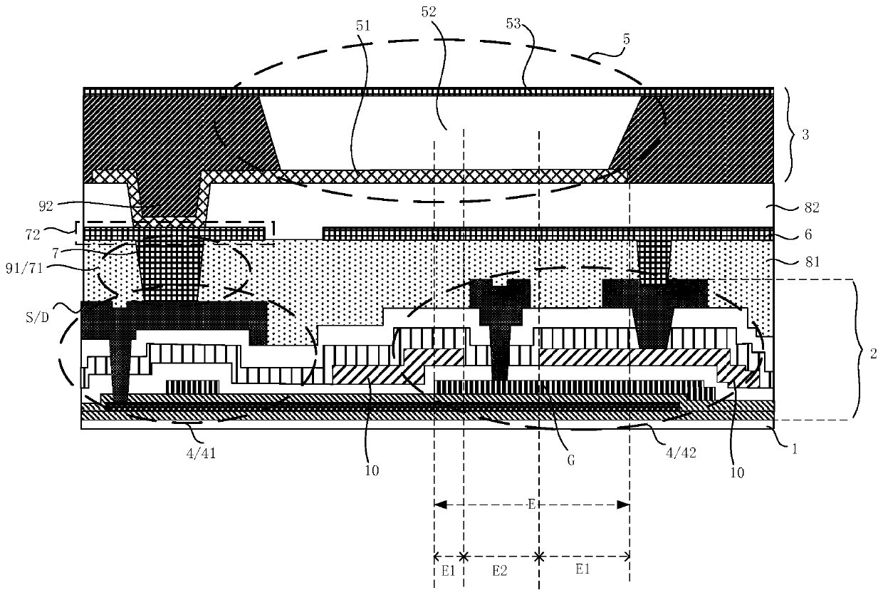
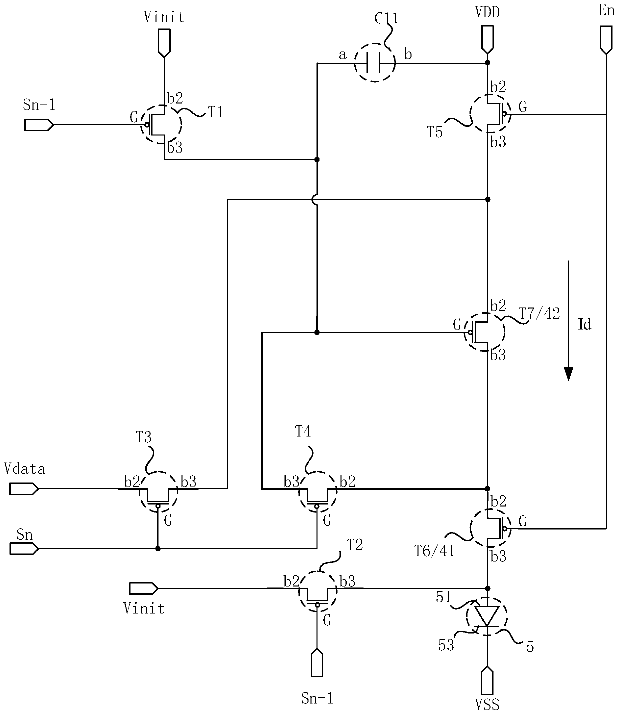
[0004] The present invention provides an organic light-emitting display panel and an organic light-emitting display device, so that the change of the potential on the lower electrode of the organic light-emitting unit will not cause the change of the potential on the gate of the thin-film transistor in the overlapping area with the lower electrode, and at the same time, the organic light-emitting device can be improved. The problem of poor contact between the lower electrode of the light emitting unit and the source or drain of the corresponding thin film transistor

Method used


Image

  • An organic light-emitting display panel and an organic light-emitting display device
  • An organic light-emitting display panel and an organic light-emitting display device
  • An organic light-emitting display panel and an organic light-emitting display device

Examples


Embodiment Construction

[0030] The present invention will be further described in detail below in conjunction with the accompanying drawings and embodiments. It should be understood that the specific embodiments described here are only used to explain the present invention, but not to limit the present invention. In addition, it should be noted that, for the convenience of description, only some structures related to the present invention are shown in the drawings but not all structures. Throughout this specification, the same or similar reference numerals represent the same or similar structures, elements or processes. It should be noted that, in the case of no conflict, the embodiments in the present application and the features in the embodiments can be combined with each other.

[0031] An embodiment of the present invention provides an organic light-emitting display panel. The organic light-emitting display panel includes a substrate, a driving circuit layer on the substrate, and an organic lig...


PUM


Abstract

The invention discloses an organic light-emitting display panel and an organic light-emitting display device. In the organic light-emitting display panel, in the direction perpendicular to a substrate, a lower electrode and a grid electrode of at least one thin film transistor in a plurality of thin film transistors are overlapped; The shielding structure located between the driving circuit layerand the lower electrode is connected to a fixed potential and is arranged in at least part of the overlapping region to shield parasitic capacitance between the grid electrode and the lower electrodeof the thin film transistor; The lower electrode is electrically connected with the source electrode or the drain electrode of at least one thin film transistor through a connecting structure, and theprojections of the connecting structure and the shielding structure on the substrate do not overlap the organic light-emitting unit. Through the technical scheme of the invention, the change of the upper potential of the lower electrode of the organic light-emitting unit cannot cause the change of the upper potential of the grid electrode of the thin film transistor overlapped with the lower electrode, and meanwhile, the problem of poor contact between the lower electrode of the organic light-emitting unit and the source electrode or the drain electrode of the corresponding thin film transistor is improved.

Description

technical field [0001] Embodiments of the present invention relate to the field of display technology, and in particular, to an organic light emitting display panel and an organic light emitting display device. Background technique [0002] OLED, Organic Light-Emitting Diode (Organic Light-Emitting Diode), also known as organic electroluminescent device, OLED has gradually occupied a place in the small-size display field due to its advantages of thinness, bendability, high contrast, and wide color gamut. Its basic structure includes an organic light-emitting unit corresponding to each pixel area and a pixel driving circuit. The organic light-emitting unit includes upper and lower electrodes and a light-emitting layer between the upper and lower electrodes. When a voltage is applied to the upper electrode and the lower electrode, holes and electrons Moving to the light-emitting layer, the two recombine in the light-emitting layer, and the excitons in the light-emitting layer ...

Claims


Application Information

Patent Timeline
IPC IPC(8): G09G3/3225H01L27/32
CPCG09G3/3208H10K59/12H10K59/126
Inventor 张露胡思明韩珍珍
Owner KUNSHAN GO VISIONOX OPTO ELECTRONICS CO LTD
Learn More