
Test method and device of flying-probe tester

A flying probe testing machine, flying probe testing technology, applied in the direction of measuring devices, electronic circuit testing, measuring electricity, etc., can solve problems such as changes, inability to detect high-precision board opening, short circuit, impact, etc., to achieve accurate testing and improve testing The effect of precision

Inactive Publication Date: 2019-04-30
HANS CNC SCI & TECH
View PDF9 Cites 3 Cited by
  • Summary
  • Abstract
  • Description
  • Claims
  • Application Information

AI Technical Summary

Problems solved by technology

Under normal circumstances, the open-circuit impedance in the parameter value of the open-short circuit test on the PCB is set to 20Ω. When the circuit resistance is greater than 20Ω, it is judged as an open circuit, and when it is less than 20Ω, it is judged as qualified. For circuits with a resistance value less than 20Ω, it cannot be accurately tested. Out of the actual resistance value, so the line below 20Ω becomes the test blind area
In actual production, it is found that some defects of PCB, such as no copper in the hole, void, thin copper, thin line, line gap, etc., will affect the resistance of the line. When the resistance is less than 20Ω, use the usual open and short circuit test When the method is used to test the above defective boards, the test results show that it is passed, but the actual resistance value changes after high-temperature welding, resulting in an open circuit problem. Therefore, the conventional test method cannot detect the open and short circuit of the high-precision board.

Method used


Image

  • Test method and device of flying-probe tester
  • Test method and device of flying-probe tester
  • Test method and device of flying-probe tester

Examples


Embodiment Construction

[0048] In order to make the purpose, technical solution and advantages of the present application clearer, the present application will be further described in detail below in conjunction with the accompanying drawings and embodiments. It should be understood that the specific embodiments described here are only used to explain the present application, and are not intended to limit the present application.

[0049] Unless otherwise defined, all technical and scientific terms used herein have the same meaning as commonly understood by one of ordinary skill in the technical field to which this application belongs. The terms used herein in the description of the application are only for the purpose of describing specific embodiments, and are not intended to limit the application. It can be understood that the terms "first", "second" and the like used in this application may be used to describe various elements herein, but these elements are not limited by these terms. These term...


PUM


Abstract

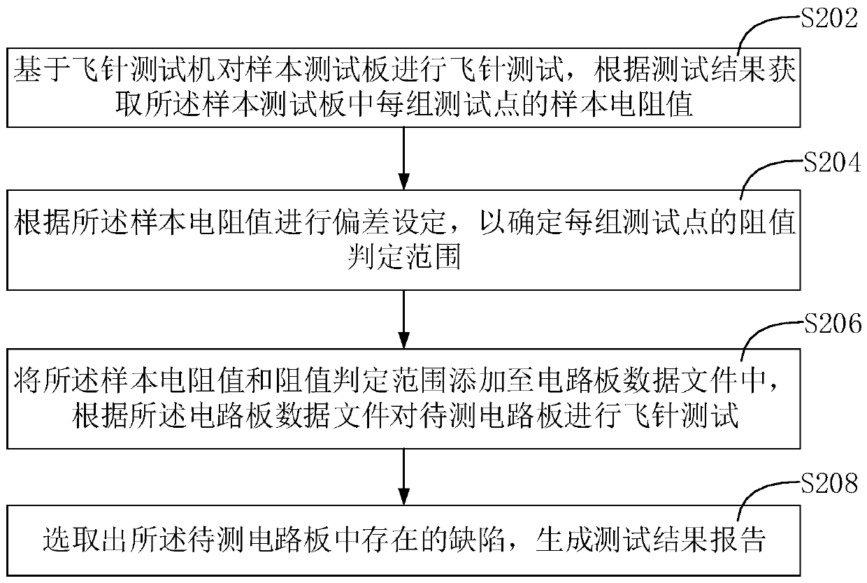
The embodiment of the invention discloses a test method and device of a flying-probe tester. The method comprises the steps of conducting a flying-probe test on a sample test board based on the flying-probe tester, and acquiring sample resistance values of each group of test points in the sample test board according to the test result; setting the deviation according to the sample resistance values so as to determine the resistance judgment range of each group of test points; adding the sample resistance values and the resistance judgment ranges to a circuit board data file, and conducting a fly-probe test on a circuit board to be tested according to the circuit board data file; and selecting defects in the circuit board to be tested, and generating a test result report. According to the method, the specific resistance value of each test point of the circuit board can be accurately measured, the test accuracy of the circuit board can be improved, and the defects of the low-resistance circuit can be accurately tested.

Description

technical field [0001] The invention relates to the technical field of printed circuit board testing, in particular to a testing method and device for a flying probe testing machine. Background technique [0002] Flying probe testing machine is an instrument for testing PCB (Printed Circuit Board, printed circuit board) with high component layout density, many layers, high wiring density and small measuring point distance. The multi-axis flying probe testing machine is composed of four completely independent moving test pins. Under the control of the software, it moves three-dimensionally on both sides of the PCB board to be tested (2 test pins on the front side and 2 test pins on the back side) and touches the point to be tested. , By applying a certain voltage and current to the test needle, different test signals are obtained, so as to judge the on-off situation of the PCB to be tested. [0003] With the rapid development of electronic technology, the number of PCB produ...

Claims


Application Information

Patent Timeline
Patent Type & Authority Applications(China)
IPC IPC(8): G01R31/28
CPCG01R31/2812
Inventor 欧阳云轩王星翟学涛杨朝辉高云峰
Owner HANS CNC SCI & TECH
Learn More