Rotating disc type thin film evaporative cooling tower

An evaporative cooling, turntable technology, applied in water shower coolers, direct contact heat exchangers, heat exchanger types, etc., can solve problems such as large differences in heat transfer coefficients, large wind resistance, and difficult implementation, and achieve improved Effect of heat transfer efficiency, reduction of ventilation resistance, and temperature reduction

Inactive Publication Date: 2019-04-30
朱玲燕
View PDF5 Cites 1 Cited by
  • Summary
  • Abstract
  • Description
  • Claims
  • Application Information

AI Technical Summary

Problems solved by technology

In the field of cooling towers, it is in the form of liquid-gas heat exchange. In the patent application number 201510396162.6, it is known that although the heat circulation The heat transfer coefficient of water heat transfer to heat storage element is 2000~4000w / m 2 .℃, but the heat transfer coefficient between the heat storage element and the cold air is only 30~60w / m 2 .℃, the heat transfer capacity of the two heat exchanges differs greatly, which makes it difficult for the heat storage element to transfer heat to the external cold air again, although the hot circulating water can easily transfer heat to the external cold air, making it difficult to implement
[0007] The heat storage element of the traditional rotary air preheater is a wavy folded plate, which has a large wind resistance and a large difference in heat transfer coefficient between the water and air sides, so it is difficult to apply to the field of cooling towers

Method used


Image

  • Rotating disc type thin film evaporative cooling tower
  • Rotating disc type thin film evaporative cooling tower
  • Rotating disc type thin film evaporative cooling tower

Examples


Embodiment Construction

[0029] Below in conjunction with specific embodiment, further illustrate the present invention. It should be understood that these examples are only used to illustrate the present invention and are not intended to limit the scope of the present invention. In addition, it should be understood that after reading the teachings of the present invention, those skilled in the art can make various changes or modifications to the present invention, and these equivalent forms also fall within the scope defined by the appended claims of the present application.

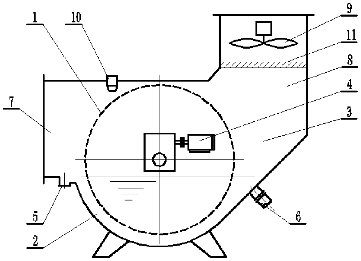
[0030] like figure 1 As shown, a turntable film evaporative cooling tower provided by the present invention includes a cooling water tank 2 connected with a circulating water inlet pipe 6 and a circulating water outlet pipe 5, and the circulating cooling water to be cooled in the cooling water tank 2. There is a cold air duct 3 above the cooling water tank 2, and the cold air duct 3 is connected with an air inlet 7 and an air ...


PUM


Abstract

The invention relates to a rotating disc type thin film evaporative cooling tower. The rotating disc type thin film evaporative cooling tower is characterized in that the rotating disc type thin filmevaporative cooling tower comprises a heat storage element driven by a driving device to rotate, the upper half part of the heat storage element is located n a cooling environment, the lower half partof the heat storage element is soaked in liquid needing to be cooled, the ambient temperature of the cooling environment is lower than the liquid temperature of the liquid needing to be cooled, whenthe heat storage element rotates, the upper half part and the lower half part of the heat storage element alternatively conduct forced-convection heat transfer with the liquid to absorb heat of the liquid, and meanwhile, the lower half part and the upper half part of the heat storage element with the liquid alternatively conduct thin film evaporation heat transfer with the cooling environment to release the absorbed heat. The purpose of lowering the temperature of circulating water is achieved by two times of heat transfer.

Description

technical field [0001] The invention relates to an open cooling tower, in particular to a rotary disc type film evaporation cooling tower. Background technique [0002] A large amount of waste heat is generated in the industrial or civil fields and needs to be discharged to the external environment. Usually, circulating cooling water is used as a component to cool the system that needs to be cooled first, take away its heat, and its own temperature rises, and then the cooling tower circulates the cooling. The water is cooled and reused. A cooling water tower is a device that cools water, in which water exchanges heat and mass with the outside air flowing through it, resulting in a drop in water temperature. It is a common industrial and civil equipment. [0003] There are many types of cooling towers. According to the ventilation mode, there are natural ventilation cooling towers and mechanical ventilation cooling towers; according to the contact mode between heat medium an...

Claims


Application Information

Patent Timeline
Patent Type & Authority Applications(China)
IPC IPC(8): F28C1/00F28D20/00
CPCF28C1/00F28D20/00Y02E60/14
Inventor 朱玲燕
Owner 朱玲燕
Why Eureka
Try Eureka