
Herringbone foundation pit supporting structure

A foundation pit support, herringbone technology, applied in the direction of foundation structure engineering, excavation, construction, etc., can solve the problems of low strength, bearing capacity depends on compressive strength, poor overall stability, etc., to achieve the reduction of pile diameter and longitudinal distribution The effect of improving the ratio of tendons, improving the distribution of internal forces, and improving stiffness and stability

Pending Publication Date: 2019-04-30
INST OF ROCK & SOIL MECHANICS CHINESE ACAD OF SCI
View PDF3 Cites 1 Cited by
  • Summary
  • Abstract
  • Description
  • Claims
  • Application Information

AI Technical Summary

Problems solved by technology

However, this structure can only be constructed after the excavation of the foundation pit is completed, and it cannot support the soil on the side wall of the foundation pit in time, so it is not suitable for deep foundation pit engineering; at the same time, the bottom end of the diagonal brace is connected to the pit bottom guard plate, and the bearing capacity Relying on the compressive strength of the bottom plate material, the strength is small and the overall stability is poor
[0004] In the prior art, the Chinese patent document with the authorized publication number CN108385692A discloses a shear key deep foundation pit support system, which includes support piles, a tension mechanism and a thrust mechanism. support, so as to achieve the purpose of saving the internal space of the foundation pit, but the construction of the waist beam of the structure is relatively complicated, and the connection method with the supporting piles is unreasonable, and it cannot be reused
[0005] In the prior art, the Chinese patent document with the authorized publication number CN107740419 discloses a foundation pit support method and inclined piles. The inclined piles of the support structure are rigidly connected with the support piles through crown beams, and the anti-resistance of the inclined piles cannot be fully utilized. The large pressure bearing capacity can not save the construction space in the pit to the maximum extent, and can not effectively reduce the maximum bending moment of the support pile

Method used


Image

  • Herringbone foundation pit supporting structure
  • Herringbone foundation pit supporting structure
  • Herringbone foundation pit supporting structure

Examples


Embodiment 1

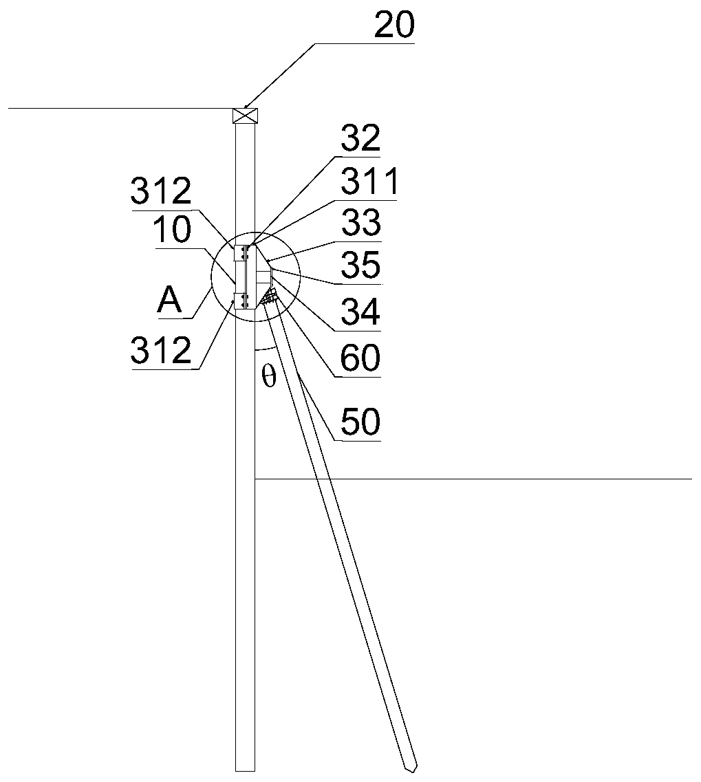
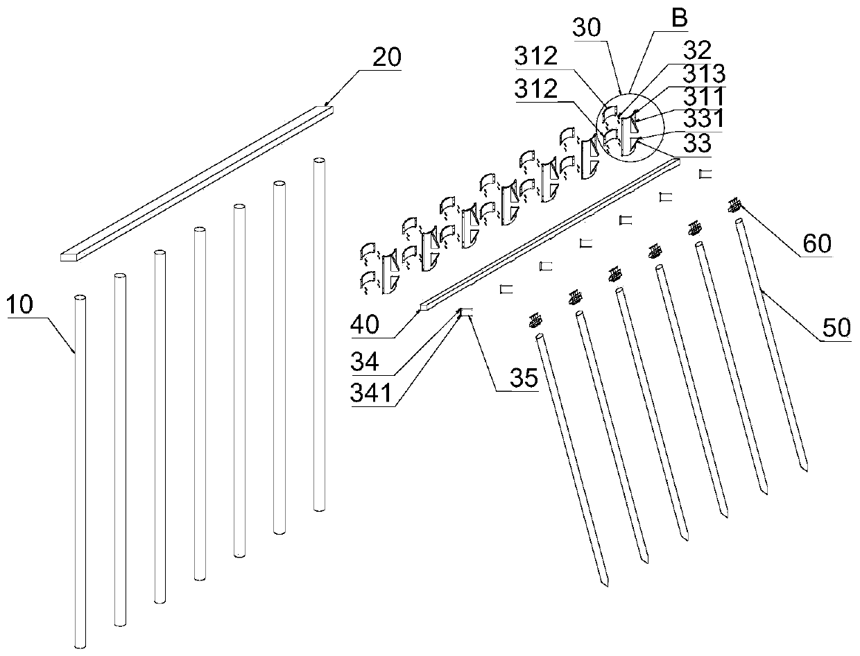
[0039] according to Figure 1a , Figure 1b , figure 2 , Figure 3a , Figure 3b , Figure 4 , Figure 5 , Image 6 It can be seen that a herringbone foundation pit support structure mainly includes upright piles 10, crown beams 20, waist beam brackets 30, locking tiles 31, front support tiles 311, rear fixed tiles 312, and bolt mounting holes 313 , locking bolt 32, waist beam card platform 33, bolt mounting hole 331, fastening pressure plate 34, bolt mounting hole 341, pressure plate fastening bolt 35, waist beam 40, inclined pile 50, active joint 60. It is characterized in that: the upright piles 10 are vertically distributed on the edge of the foundation pit to be excavated, and the tops of the piles are connected by pouring crown beams to jointly bear the soil pressure outside the foundation pit, and a waist beam bracket 30 is installed at the waist of the upright piles 10 . The waist beam bracket 30 is a prefabricated component, and the waist beam bracket 30 includ...

Embodiment 2

[0051] according to Figure 7a with Figure 7b It can be seen that a herringbone foundation pit support structure mainly includes upright piles 10, crown beams 20, waist beam brackets 30, locking tiles 31, front support tiles 311, rear fixed tiles 312, and bolt mounting holes 313 , locking bolt 32, waist beam card platform 33, bolt mounting hole 331, fastening pressure plate 34, bolt mounting hole 341, pressure plate fastening bolt 35, first waist beam 41, second waist beam 42, first inclined pile 51 , the second inclined pile 52, the active joint 60. It is characterized in that: the upright piles 10 are vertically distributed on the edge of the foundation pit to be excavated, the tops of the piles are connected by pouring crown beams, and jointly bear the soil pressure outside the foundation pit, the first waist beam position and the second waist beam position are respectively installed with waist beam supports Seat 30.

[0052] The waist beam bracket 30 is a prefabricated...

Embodiment 3

[0063] according to Figure 8a with Figure 8b It can be seen that a herringbone foundation pit support structure mainly includes upright piles 10, crown beams 20, waist beam brackets 30, locking tiles 31, front support tiles 311, rear fixed tiles 312, and bolt mounting holes 313 , locking bolt 32, waist beam card platform 33, bolt mounting hole 331, fastening pressure plate 34, bolt mounting hole 341, pressure plate fastening bolt 35, waist beam 40, inclined pile 50, active joint 60. It is characterized in that: the upright piles 10 are vertically distributed on the edge of the foundation pit to be excavated, the tops of the piles are connected by pouring crown beams, and jointly bear the soil pressure outside the foundation pit, the first waist beam position and the second waist beam position are respectively installed with waist beam supports Seat 30.

[0064] The waist beam bracket 30 is a prefabricated component, and the waist beam bracket 30 includes a locking tile 31,...


PUM


Abstract

The invention discloses a herringbone foundation pit supporting structure. Vertical piles are vertically distributed at the edge of a foundation pit to be excavated; top beams are poured at the tops of the vertical piles; a wale bracket is mounted at the waist of each vertical pipe; the wale bracket comprises a locking tile, a locking bolt, a wale clamping platform, a fastening pressing plate anda pressing plate fastening bolt; the locking tile comprises a front part support pile and a rear part fixed pile; bolt mounting holes are symmetrically formed at the edge of the locking pile and fix the locking pile to the vertical pile; the wale clamping platform comprises a pair of right-angled trapezoid ribbed plates which are welded with the front part support pile; a bolt mounting hole is formed in the top of each right-angled trapezoid ribbed plate; a pair of bolt mounting holes are formed in the fastening pressing plate; a fastening bolt sequentially penetrates through the bolt mountinghole in the fastening pressing plate and the bolt mounting hole in the wale clamping platform, so as to fasten a wale to the wale clamping platform. The wale is fixed on the wale clamping platform, and the lower part of a pile body is inserted to the deep position of the bottom in the pit. The foundation pit supporting structure is simple, compact, high in integrality and reliability, good in self-stabilization, and small in occupied space.

Description

technical field [0001] The invention belongs to the technical field of foundation pit support structures, and more specifically relates to a foundation pit support structure, which is suitable for large-area deep foundation pit support projects and ensures safety and stability during foundation pit construction. Background technique [0002] In recent years, in order to meet the needs of national development and people's pursuit of a high-level life, high-rise, super high-rise buildings, urban rail transit projects, underground shopping malls, parking lots and other underground projects have rapidly increased, and the depth of foundation pits has become more and more The foundation soil in the coastal area is soft soil with high water content and low bearing capacity. In order to ensure the stability during the excavation of the foundation pit, the enclosure structure of the foundation pit needs to bear a large lateral load. earth pressure. The traditional deep foundation p...

Claims


Application Information

Patent Timeline
Patent Type & Authority Applications(China)
IPC IPC(8): E02D17/04
CPCE02D17/04
Inventor 陈从新张亚鹏雷美清郑允邵勇
Owner INST OF ROCK & SOIL MECHANICS CHINESE ACAD OF SCI
Learn More