A sorting device for shock absorbing springs of electric vehicles
A shock-absorbing spring, electric vehicle technology, applied in classification, solid separation, chemical instruments and methods, etc., can solve the problems of sorting, no way to spring, etc.
- Summary
- Abstract
- Description
- Claims
- Application Information
AI Technical Summary
Problems solved by technology
Method used
Image

Examples
specific Embodiment approach 1
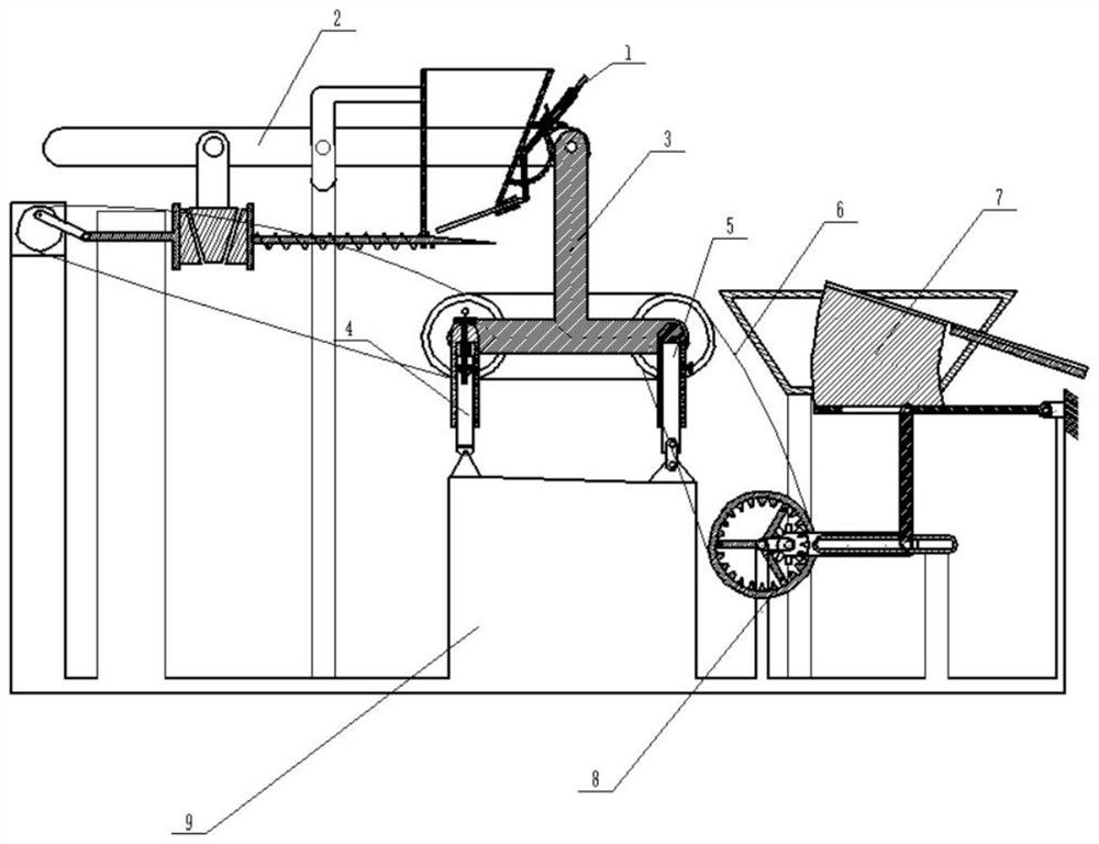
[0035] Combine below Figure 1-14 Describe this embodiment, a sorting device for shock absorbing springs of electric vehicles, including a spring feeding bin 1, a wall bar 2, a transport assembly 3, a left end adjustment bracket 4, a right end adjustment bracket 5, a timing belt 6, and a sorting bin 7. The movement rod assembly 8 and the frame 9, the spring feeding bin 1 is hingedly connected with the wall rod 2, the transport assembly 3 is hingedly connected with the wall rod 2, the left end adjustment bracket 4 is fixedly connected with the transport assembly 3, and the right end The adjustment bracket 5 is hingedly connected to the transport assembly 3, the synchronous belt 6 is connected to the wall bar 2 and the movement bar assembly 8 through the transport assembly 3, and the frame 9 is fixedly connected to the spring feeding bin 1, the wall bar 2, and the transport assembly The lower end of body 3, left end adjustment support 4, right end adjustment support 5, synchrono...
specific Embodiment approach 2
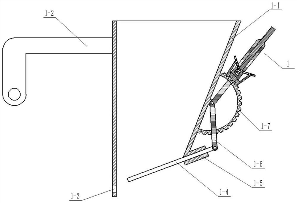
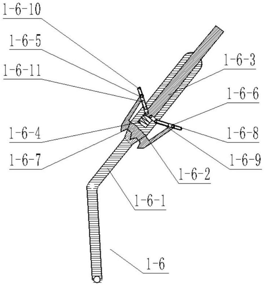
[0037] Combine below Figure 1-14 Describe this embodiment, this embodiment will further explain Embodiment 1. The spring feeding bin 1 includes a spring feeding bin body 1-1, a hinge rod 1-2 at the left end of the feeding bin, and a sliding hole 1-2 at the left end of the feeding bin. 3. Hatch door panel 1-4, hatch panel slide frame 1-5, right end connecting rod 1-6 and arc rod 1-7, described right end connecting rod 1-6 includes connecting rod body 1-6-1, arc-shaped Clamping rod 1-6-2, inner end sliding rod 1-6-3, inner end compression spring 1-6-4, hinged connecting rod Ⅰ1-6-5, hinged connecting rod Ⅱ1-6-6, arc card slot 1-6-7, hinged connecting rod waist groove Ⅰ 1-6-8, hinged connecting rod waist groove Ⅱ 1-6-9, hinged connecting rod waist groove Ⅲ 1-6-10 and hinged connecting rod waist groove Ⅳ 1-6-11, The inner sliding rod 1-6-3 is slidingly connected with the connecting rod body 1-6-1, the arc clamping rod 1-6-2 is arranged on the front end of the connecting rod body ...
specific Embodiment approach 3
[0039] Combine below Figure 1-14 Describe this embodiment, this embodiment will further explain Embodiment 1, the wall rod 2 includes the upper end rod 2-1 of the wall rod, the middle hinge rod 2-2, the middle end roller cone 2-3, and the left end inclined push plate 2 -4, right end inclined-plane push plate 2-5, right end push rod 2-6, right end plate 2-7, sleeve spring 2-8, left end bar 2-9, motor connecting rod 2-10, input motor 2-11 and input The runner 2-12, the upper end of the middle end hinged rod 2-2 is hingedly connected to the middle end of the upper end rod 2-1 of the wall rod, and the middle end roller cone 2-3 is fixedly connected to the lower end of the middle end hinged rod 2-2, the left end Inclined push plate 2-4 is fixedly connected with left end bar 2-9, and right end inclined plane push plate 2-5 is fixedly connected with right end push rod 2-6, and right end plate 2-7 is fixedly connected with the right end of right end push rod 2-6, sleeve The spring 2...
PUM
 Abstract
Description
Claims
Application Information
 - Generate Ideas
- Intellectual Property
- Life Sciences
- Materials
- Tech Scout
- Unparalleled Data Quality
- Higher Quality Content
- 60% Fewer Hallucinations
Browse by: Latest US Patents, China's latest patents, Technical Efficacy Thesaurus, Application Domain, Technology Topic, Popular Technical Reports.
© 2025 PatSnap. All rights reserved.Legal|Privacy policy|Modern Slavery Act Transparency Statement|Sitemap|About US| Contact US: help@patsnap.com