
Control method, system and device for auxiliary power supply system

A technology of auxiliary power supply and control method, which is applied in the direction of electrical components, output power conversion devices, single-network parallel feeding arrangements, etc., and can solve problems such as weakened switch circulation, severe switch circulation, and large reactor volume

Active Publication Date: 2019-04-26
SHENZHEN INVT TRANSPORTATION TECH CO LTD
View PDF6 Cites 3 Cited by
  • Summary
  • Abstract
  • Description
  • Claims
  • Application Information

AI Technical Summary

Problems solved by technology

However, in the traditional auxiliary power system without interconnection wires, there is generally no way to eliminate the switching circulation, and only rely on the reactor at the output end of the inverter to weaken the switching circulation.
And because the reactor at the output end of the inverter is large in size and expensive to manufacture, in practical engineering applications, the method of reducing the impedance is often used to reduce the size of the reactor, which leads to the problem of switch circulation becoming more and more serious

Method used


Image

  • Control method, system and device for auxiliary power supply system
  • Control method, system and device for auxiliary power supply system
  • Control method, system and device for auxiliary power supply system

Examples


Embodiment Construction

[0048] The core of the invention is to provide a control method for the auxiliary power system, which effectively reduces the switch circulation of the auxiliary power system.

[0049] In order to enable those skilled in the art to better understand the solution of the present invention, the present invention will be further described in detail below in conjunction with the accompanying drawings and specific embodiments. Apparently, the described embodiments are only some of the embodiments of the present invention, but not all of them. Based on the embodiments of the present invention, all other embodiments obtained by persons of ordinary skill in the art without making creative efforts belong to the protection scope of the present invention.

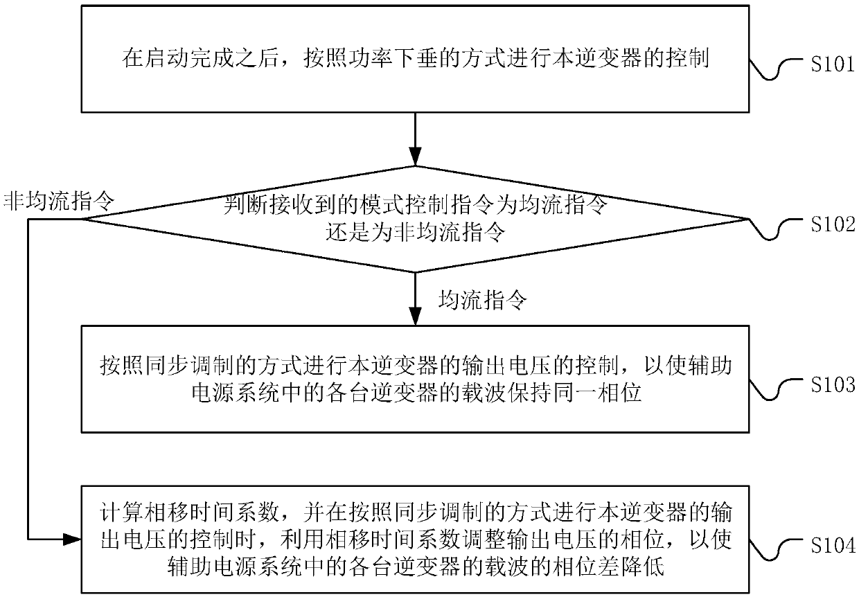
[0050] Please refer to figure 2 , figure 2 It is an implementation flowchart of a control method of an auxiliary power supply system in the present invention, the method is applied to each parallel inverter, including:

[0051] St...


PUM


Abstract

The invention discloses a control method for an auxiliary power supply system. The method is applied to each parallel inverter and comprises controlling the inverter in a power drop mode after startup; judging whether a received mode control command is a current sharing command or a non-current sharing command; if the command is the current sharing command, controlling the output voltage of the inverter in a synchronous modulation manner so that carriers of all the inverters in the auxiliary power supply system are maintained at the same phase; if the command is the non-current sharing command, calculating the phase shift time coefficient, utilizing the phase shift time coefficient to adjust the phase of the output voltage when the output voltage of the current inverter is controlled according to the synchronous modulation mode to reduce the phase difference of the carriers of the inverters in the auxiliary power supply system. By means of the scheme, the switching loop current of theauxiliary power system is effectively reduced. A control system and device for the auxiliary power supply system is further disclosed, and corresponding technical effects are achieved.

Description

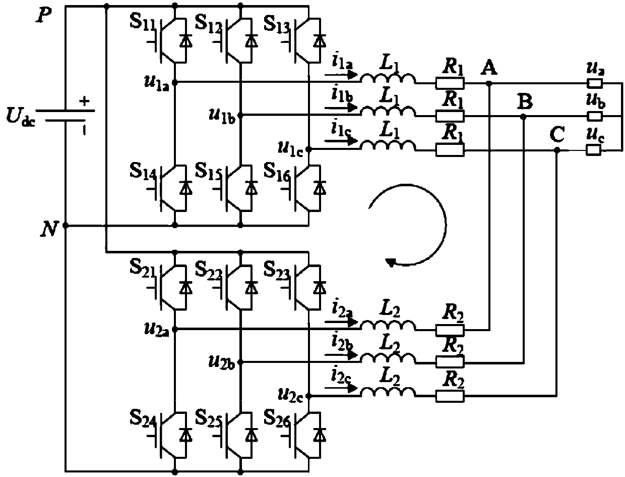
technical field [0001] The present invention relates to the technical field of power electronics, in particular to a control method, system and equipment for an auxiliary power supply system. Background technique [0002] Auxiliary power supply is a common equipment on traffic operation vehicles. It is used to transmit electric energy to equipment such as lighting, air conditioning, and control systems. Its safety and reliability are particularly important. [0003] In order to ensure that the auxiliary power supply can operate normally in the island mode, the grid-connected inverter in the auxiliary power supply system usually adopts a constant frequency and constant voltage control method. At the same time, a redundant configuration scheme is usually used in the design of the auxiliary power supply system. In order to ensure the stable operation of the power supply network, that is, usually multiple inverters with a common DC bus are operated in parallel. figure 1 A schem...

Claims


Application Information

Patent Timeline
IPC IPC(8): H02M7/5387H02J3/38
CPCH02J3/38H02M7/53871
Inventor 邓知先程梦来杨北辉
Owner SHENZHEN INVT TRANSPORTATION TECH CO LTD
Learn More