
display device

A technology of display device and light source, which is applied in the direction of visual time indicating device, indicating time, transportation and packaging, etc., can solve the problem of increasing the size of the frame, and achieve the effect of improving lighting

Active Publication Date: 2022-03-08
LG DISPLAY CO LTD
View PDF5 Cites 0 Cited by
  • Summary
  • Abstract
  • Description
  • Claims
  • Application Information

AI Technical Summary

Problems solved by technology

However, in this case the size of the bounding box increases

Method used


Image

  • display device
  • display device
  • display device

Examples


Embodiment Construction

[0038] Hereinafter, exemplary embodiments of an organic light emitting display device according to the present invention will be described in detail with reference to the accompanying drawings so that the present invention will be easily realized by those skilled in the art. In the drawings, the same elements are denoted by the same reference numerals even if they are drawn in different drawings. In the following description of the present invention, detailed descriptions of known functions and configurations incorporated herein will be omitted when they may obscure the subject matter of the present invention. Those skilled in the art will appreciate that some features in the drawings may be exaggerated, reduced or simplified for ease of description, and that the drawings and elements of the drawings are not always shown to exact scale.

[0039] image 3 is a front view showing a handheld terminal provided with a display device according to a first embodiment of the present i...


PUM


Abstract

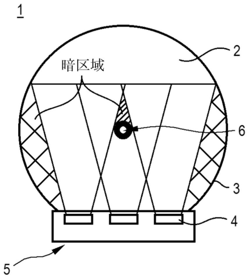
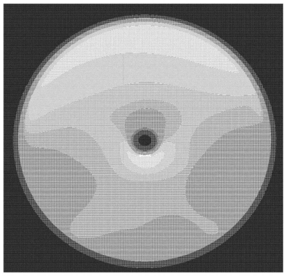
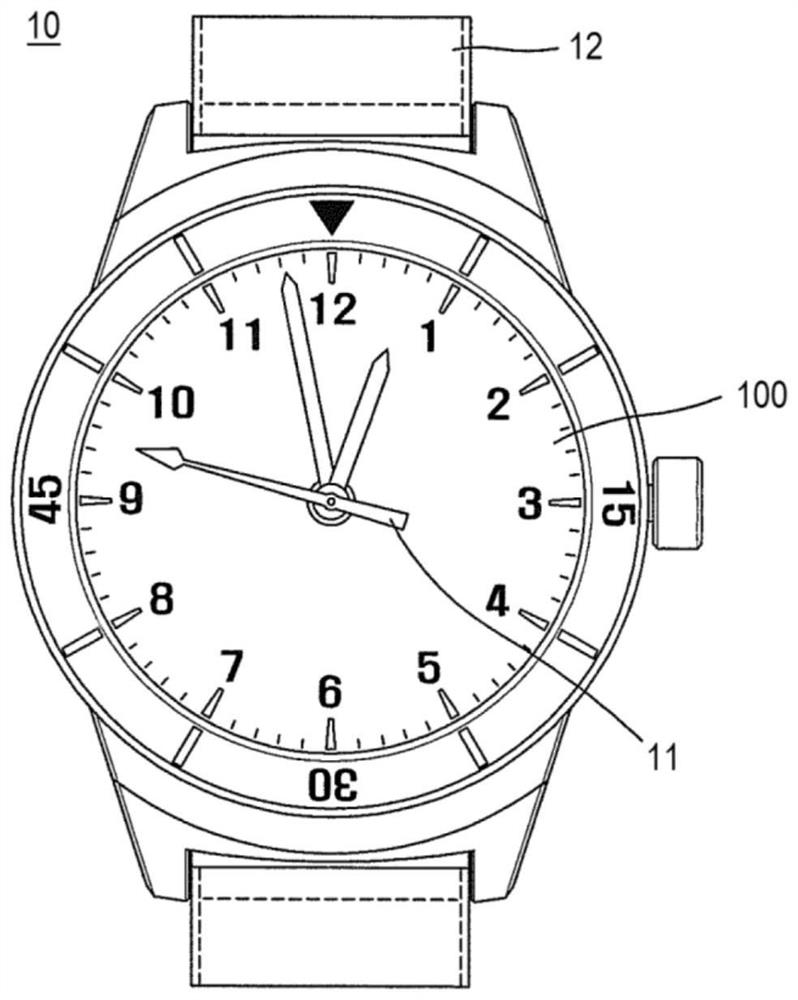
A display device configured such that a through hole extends through a liquid crystal panel and a light guide plate, a fastener for coupling a watch hand to the through hole is coupled to the through hole, and the fastener is prevented from contacting the through hole. Interference between surrounding light from light sources creates dark areas. At least one flat side surface for minimizing interference with light from the light source is provided on the fastener, thereby providing uniform brightness around the through hole.

Description

[0001] This application claims the benefit of Korean Patent Application No. 10-2017-0135772 filed on October 19, 2017 and Korean Patent Application No. 10-2017-0176119 filed on December 20, 2017, which are incorporated herein by reference , as fully set forth herein. technical field [0002] The present invention relates to a display device configured such that a through hole coupled with a rotatable hand of a watch is provided at the center of a liquid crystal panel. Background technique [0003] Recently, in an information-oriented society, the importance of a display device as a visual information transmission medium has been further emphasized. In order to occupy an important position in the future, requirements such as low power consumption, slimness, weight reduction, and high image quality must be met. [0004] Display devices can be classified into self-luminous display devices (for example, cathode ray tube (CRT) display devices, electroluminescence (EL) display de...

Claims


Application Information

Patent Timeline
Patent Type & Authority Patents(China)
IPC IPC(8): G02F1/13357G02B6/00G04G9/12
CPCG02B6/0055G02F1/133615G04G9/126G04G9/0094G02F2201/56G04C17/0091G04G9/0041G04G17/045G02B6/0011G02B6/009G02B6/0078G02F1/133606G02F1/133611B60K35/00B60K35/60G02B6/0031G02B6/0068G02F1/133553G02F1/133603
Inventor 全世桓吴金泳吴智淳
Owner LG DISPLAY CO LTD
Learn More