Automatic measuring device based on laser reference plane
A laser reference and measuring device technology, applied in the direction of active optical measuring devices, measuring devices, measuring instruments, etc., can solve the problems of increased measurement costs, errors in the actual situation of bridges, and incremental measurement costs, and achieve the effect of accurate displacement measurement
- Summary
- Abstract
- Description
- Claims
- Application Information
AI Technical Summary
Problems solved by technology
Method used
Image


Examples
Embodiment 1
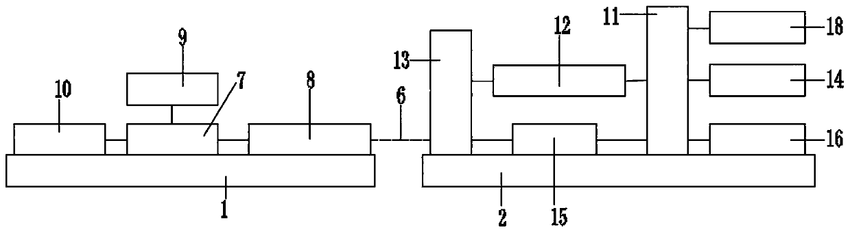
[0044] This embodiment discloses an automatic measuring device based on a laser reference plane, such as figure 1 As shown, it includes a laser emitting end 3 located at the reference point 1 and a laser receiving end 4 located at the point to be measured 2, the laser emitting end 3 emits a laser signal 6 at the reference point 1, and the laser receiving end 4 at the reference point 1 The point 2 to be measured intersects the surface laser signal 6, and the laser receiving end 4 is connected to the laser emitting end 3 in communication; when working, the laser receiving end 4 is used to analyze the received laser signal and send the analysis result to the laser emitting end 3.
[0045] In this embodiment, the number of the laser emitting end 3 is one, and the number of the laser receiving end 4 is at least one, that is, one laser emitting end 3 can correspond to a plurality of laser receiving ends 4 at the same time, and a plurality of laser receiving ends 4 Cooperate with th...
Embodiment 2
[0060] This embodiment discloses an automatic measuring device based on a laser reference plane, such as figure 1 As shown, it includes a laser emitting end 3 located at the reference point 1 and a laser receiving end 4 located at the point to be measured 2, the laser emitting end 3 emits a laser signal 6 at the reference point 1, and the laser receiving end 4 at the reference point 1 The point 2 to be measured intersects the surface laser signal 6, and the laser receiving end 4 is connected to the laser emitting end 3 in communication; when working, the laser receiving end 4 is used to analyze the received laser signal and send the analysis result to the laser emitting end 3.
[0061]In this embodiment, the number of the laser emitting end 3 is one, and the number of the laser receiving end 4 is at least one, that is, one laser emitting end 3 can correspond to a plurality of laser receiving ends 4 at the same time, and a plurality of laser receiving ends 4 Cooperate with the...
Embodiment 3
[0068] This embodiment discloses an automatic measuring device based on a laser reference plane, such as figure 1 As shown, it includes a laser emitting end 3 located at the reference point 1 and a laser receiving end 4 located at the point to be measured 2, the laser emitting end 3 emits a laser signal 6 at the reference point 1, and the laser receiving end 4 at the reference point 1 The point 2 to be measured intersects the surface laser signal 6, and the laser receiving end 4 is connected to the laser emitting end 3 in communication; when working, the laser receiving end 4 is used to analyze the received laser signal and send the analysis result to the laser emitting end 3.
[0069] In this embodiment, the number of the laser emitting end 3 is one, and the number of the laser receiving end 4 is at least one, that is, one laser emitting end 3 can correspond to a plurality of laser receiving ends 4 at the same time, and a plurality of laser receiving ends 4 Cooperate with th...
PUM
 Abstract
Description
Claims
Application Information
 - R&D
- Intellectual Property
- Life Sciences
- Materials
- Tech Scout
- Unparalleled Data Quality
- Higher Quality Content
- 60% Fewer Hallucinations
Browse by: Latest US Patents, China's latest patents, Technical Efficacy Thesaurus, Application Domain, Technology Topic, Popular Technical Reports.
© 2025 PatSnap. All rights reserved.Legal|Privacy policy|Modern Slavery Act Transparency Statement|Sitemap|About US| Contact US: help@patsnap.com