
Method for detecting roadbed strain by optical fiber sensing technology

A technology of optical fiber sensing and technical detection, which is applied in the survey of on-site foundation soil, roads, roads, etc., can solve the problems of inability to realize all-round detection of the measured object, sparse measurement points, low accuracy, etc., and achieve unmanned On-duty automatic monitoring and data collection, the realization of remote detection, and the effect of simplifying the detection steps

Inactive Publication Date: 2019-04-26
CHINA RAILWAY 20 BUREAU GRP +1
View PDF2 Cites 7 Cited by
  • Summary
  • Abstract
  • Description
  • Claims
  • Application Information

AI Technical Summary

Problems solved by technology

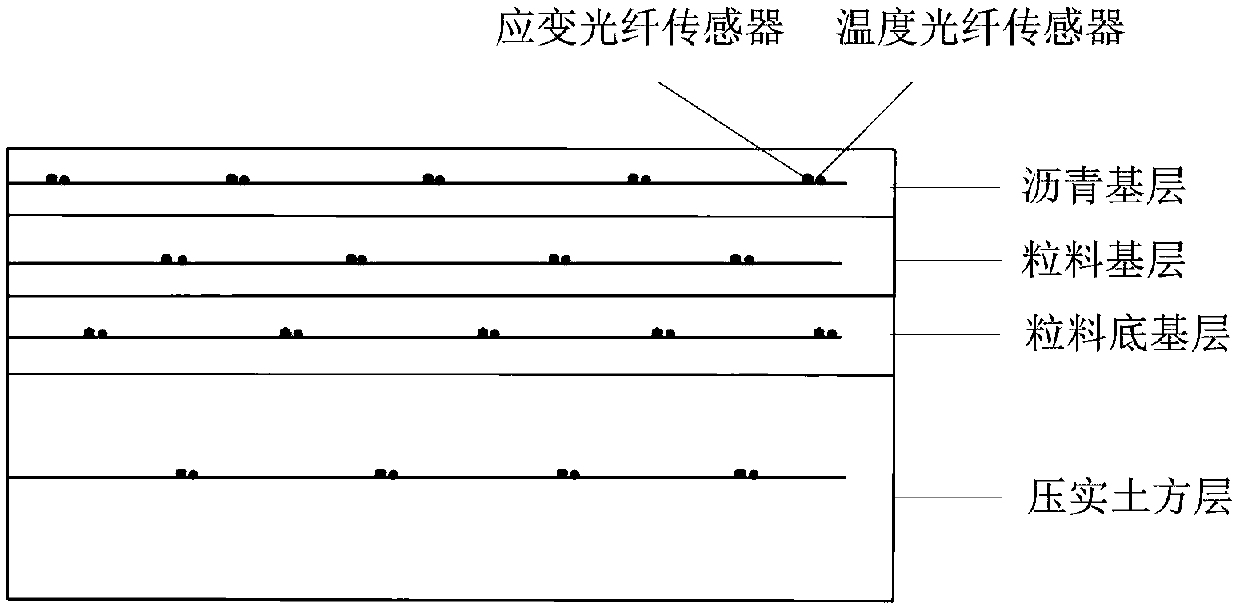
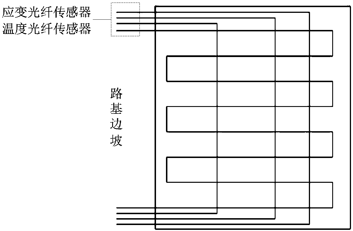
[0004] In view of the low accuracy, cumbersome detection steps, and sparse measurement points in the existing technology, it is impossible to realize the all-round detection of the measured object, and the sensors used in the existing technology are easy to corrode, and it is difficult to realize the technology of long-term monitoring Problem, the present invention provides a detection method of subgrade strain optical fiber sensing technology, which can improve the detection accuracy of subgrade strain, simplify the detection steps, comprehensively control the deformation characteristics of subgrade during the construction period and operation period, and realize unmanned On-duty automatic monitoring and data collection to achieve remote detection, and the sensors used in this method have the advantages of anti-corrosion, anti-electromagnetic interference, and large amount of information, which can realize long-term monitoring

Method used


Image

  • Method for detecting roadbed strain by optical fiber sensing technology
  • Method for detecting roadbed strain by optical fiber sensing technology
  • Method for detecting roadbed strain by optical fiber sensing technology

Examples


Embodiment Construction

[0020] The specific implementation manners of the embodiments of the present invention will be described in detail below in conjunction with the accompanying drawings. It should be understood that the specific implementation manners described here are only used to illustrate and explain the embodiments of the present invention, and are not intended to limit the embodiments of the present invention.

[0021] It should be noted that, in the case of no conflict, the embodiments of the present invention and the features in the embodiments can be combined with each other.

[0022] In the present invention, unless stated to the contrary, the used orientation words such as "up, down, top, bottom" generally refer to the directions shown in the drawings or refer to the vertical, perpendicular or gravitational directions The terms used to describe the mutual positional relationship of the various components mentioned above.

[0023] The present invention will be described in detail bel...


PUM


Abstract

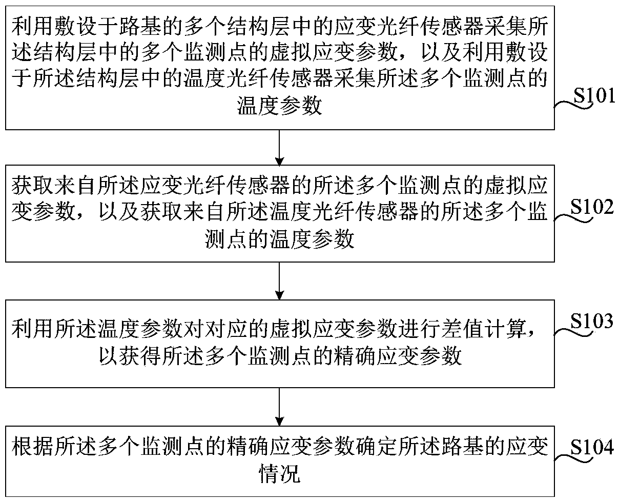
The invention provides a method for detecting the roadbed strain by an optical fiber sensing technology. The method comprises the following steps: collecting virtual strain parameters of multiple monitoring points in a structural layer by utilizing a strain optical fiber sensor in multiple structural layers of roadbed, and collecting temperature parameters of multiple monitoring points by utilizing a temperature optical fiber sensor laid in the structural layer; acquiring virtual strain parameters from multiple monitoring points of a strain optical sensor, and acquiring temperature parametersfrom multiple monitoring points of a temperature optical sensor; calculating the differential value of corresponding virtual strain parameters by utilizing the temperature parameters to obtain accurate strain parameters of the multiple monitoring points; and determining the strain situation of the roadbed according to the accurate strain parameters of multiple monitoring points. According to the method, the detection steps can be simplified, deformation characteristics of the roadbed in the constructing period and operation period can be completely mastered, automatic monitoring and data collection of unattended operation can be realized, and far-distance detection can be realized.

Description

technical field [0001] The invention relates to the field of municipal engineering construction, in particular to a detection method of roadbed strain optical fiber sensing technology. Background technique [0002] my country's highway engineering infrastructure is in a period of large-scale construction. In order to ensure that the smoothness of the road surface meets the requirements of technical specifications and predict the stability of each structural layer of the roadbed, it is necessary to detect the settlement and cracking of the roadbed during construction and operation. Overall health status perception and monitoring. The use of detection data can achieve a certain degree of trend forecasting and early warning, and guide disaster prevention and mitigation and construction reinforcement work to avoid disasters as much as possible and reduce the impact of disasters. [0003] In the prior art, subsidence instruments, inclinometers, total stations, and levels are main...

Claims


Application Information

Patent Timeline
Patent Type & Authority Applications(China)
IPC IPC(8): E01C3/00E02D1/00
CPCE01C3/00E02D1/00
Inventor 李洁勇宋占璞杨铁晖冯时松乔飞
Owner CHINA RAILWAY 20 BUREAU GRP
Learn More