
Fire coal conveying device

A conveying device and coal-fired technology, which is applied in the direction of conveyors, conveyor objects, transportation and packaging, etc., can solve the problems of large space occupation, waste of energy consumption, high production costs, etc., to reduce floor space, reduce energy consumption, The effect of reducing production costs

Active Publication Date: 2019-04-26
湖州加怡新市热电有限公司
View PDF9 Cites 0 Cited by
  • Summary
  • Abstract
  • Description
  • Claims
  • Application Information

AI Technical Summary

Problems solved by technology

[0004] The disadvantage of the existing technology is that coal storage bunkers generally need to store four to five tons of coal, so that the coal storage bunkers are generally three stories high. The second floor is used to store coal-fired warehouses, so it is necessary to use inclined conveyors to transport the coal-fired coal in the warehouse to the third floor, so that it can be transported to the coal storage bunker for temporary storage; and thermal power plants are generally equipped with multiple groups There are multiple sets of boilers and coal storage bunkers, so generally multiple sets of conveyors corresponding to the coal storage bunkers are used to transport the coal, which not only wastes a lot of energy consumption, but also takes up too much space for multiple sets of conveyors , higher production cost

Method used


Image

  • Fire coal conveying device
  • Fire coal conveying device
  • Fire coal conveying device

Examples


Embodiment 2

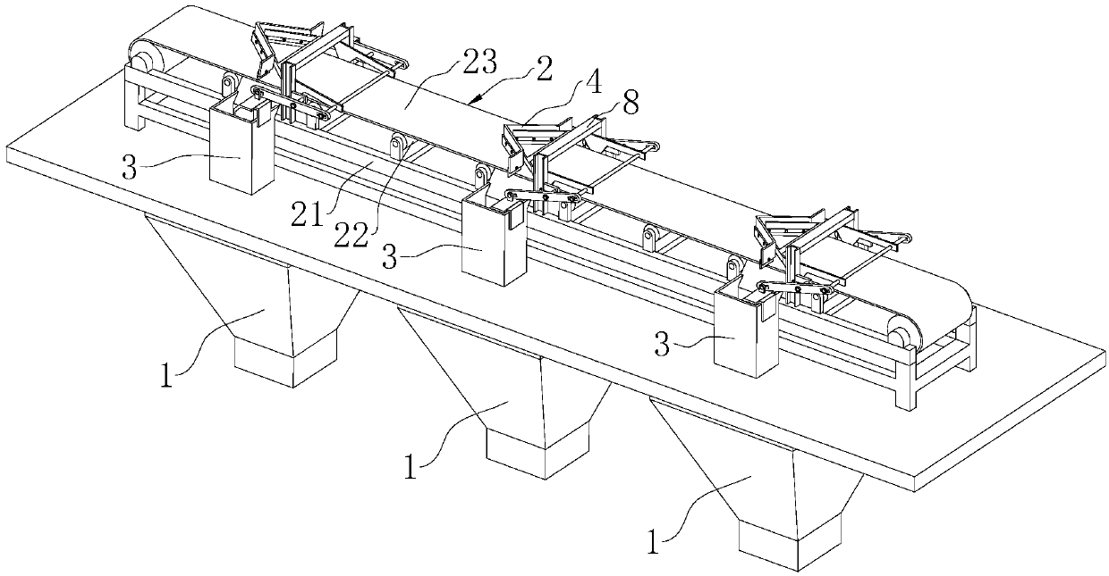
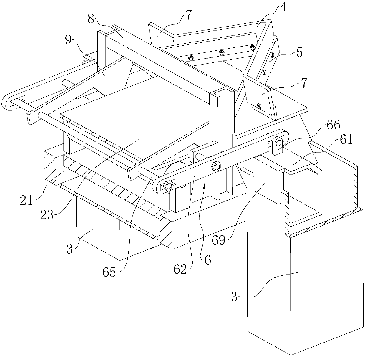
[0037] Embodiment 2: refer to Figure 4 The difference from Embodiment 1 is that the driving member 6 includes a hollow counterweight frame 61, a connecting rod 62 and a rotating shaft 611, the counterweight frame 61 is arranged in the coal storage bin 1, and the connecting rod 62 passes through the floor and the The upper end of the counterweight frame 61 is vertically fixed, and the rotating shaft 611 is fixed parallel to the width direction of the frame 21 above the end of the baffle plate 4 at the sharp corner; the upper end of the connecting rod 62 is provided with an arc-shaped groove 610 for the rotating shaft 611 to be plugged in and displaced. ; In this embodiment, the connecting rod 62 can only move vertically up and down under the limit effect of the floor; When there is less coal in the coal storage bin 1, the counterweight frame 61 hangs down freely, and under the gravity of the counterweight frame 61, the rubber pad 5 is driven to contact the conveyor belt 23; wh...


PUM


Abstract

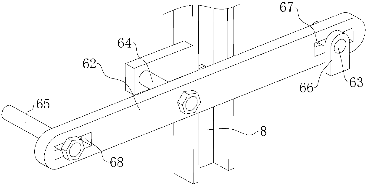
The invention relates to a fire coal conveying device. The conveying device comprises a first conveyor, a second conveyor and multiple sets of coal storage bins arranged in a manner of corresponding to a hearth, the first conveyor is arranged in an inclined manner, the lower side of the first conveyor communicates with a warehouse, the higher side of the first conveyor is located above one side ofthe second conveyor, the coal storage bins are arranged in parallel in the length direction of the second conveyor, each coal storage bin is provided with two guide hoppers arranged in the width direction of the conveyors, multiple guide devices used for guiding fire coal on the second conveyor into the corresponding guide hoppers are correspondingly arranged on the second conveyor, each guide device comprises a supporting frame, a baffle, a support used for mounting of the baffle and rotatably connected to the supporting frame, and a driving part used for driving the support to turn over inthe vertical direction of the second conveyor, and the supporting frame and the baffle are fixed to the second conveyor; two ends of the baffles extend out of the second conveyor, under the driving effect of the driving parts, the baffles are in abut joint with a conveying belt of the second conveyor or away from the conveying belt; and the effects that the occupied area of the conveyors can be reduced, energy losses are reduced, and the production cost is reduced are achieved.

Description

technical field [0001] The invention relates to the technical field of thermal power plant boilers, in particular to a coal-fired conveying device. Background technique [0002] The current circulating fluidized bed boiler technology is a high-efficiency, low-pollution and clean combustion technology that has developed rapidly in the past ten years. Internationally, this technology has been widely used commercially in the fields of power station boilers, industrial boilers and waste treatment and utilization, and is developing towards large-scale circulating fluidized bed boilers with a scale of hundreds of thousands of kilowatts; domestic research and development in this area And applications are also gradually emerging, and hundreds of circulating fluidized bed boilers have been put into operation or are being manufactured. The next few years will be an important period for the rapid development of circulating fluidized beds. [0003] The circulating fluidized bed uses c...

Claims


Application Information

Patent Timeline
Patent Type & Authority Applications(China)
IPC IPC(8): B65G65/32B65G23/04B65G47/34
CPCB65G23/04B65G47/34B65G65/32
Inventor 周滨阮云生徐斌
Owner 湖州加怡新市热电有限公司
Learn More