
Single rotor wing unmanned aerial vehicle

A drone and single-rotor technology, applied in the field of drones, can solve problems such as output shaft vibration, imprecise meshing of the driven gear plate, deflection and rotation set value errors, etc., to avoid axial creep and prevent The effect of turning the belt over to ensure stability

Inactive Publication Date: 2019-04-26
SUZHOU LINGSU ELECTRONICS TECH CO LTD
View PDF0 Cites 1 Cited by
  • Summary
  • Abstract
  • Description
  • Claims
  • Application Information

AI Technical Summary

Problems solved by technology

[0002] Single-rotor drones, also known as helicopter drones, fly through the main rotor and change the direction of deflection through the tail rotor. Compared with multi-rotor or fixed-wing drones, they have the characteristics of strong maneuverability and fast flight speed. , so in the field of competition, helicopter UAV has always been a relatively popular model, and the main rotor mechanism of helicopter UAV is the power source of the whole UAV, so the main rotor mechanism needs excellent stability for To ensure the stable flight of the UAV, when the main rotor rotates, due to the large centrifugal force, the deflection of the main rotor may not be completed smoothly, or the deflection cannot reach the predetermined angle. The main rotor mechanism of the existing helicopter UAV, its main The deflection connection of the propeller clamp is completed by installing thrust bearings and ordinary roller bearings. The thrust bearing bears its centrifugal force. However, due to the large axial clearance of the thrust bearing, in actual use, the deflection and rotation of the main rotor are related to the There is a certain error in the set value; the tail mechanism plays a role in counteracting the reaction force when the main rotor rotates, prevents the straight plane from rotating, and is also used to ensure that the straight plane has a stable flight direction. In the prior art, the transmission of the tail wing rotation is a gear The transmission requires high mechanical precision, and the failure rate and damage rate are high; the deflection structure of the empennage is completed by a hinged structure, which requires relatively high precision, and the transmission smoothness of the mechanism is not high. The structure is a radial fixed mode, and it will be directly damaged when the straight machine falls;
[0003] The fuselage mechanism of the drone is related to the flight speed, stability and drop resistance of the entire drone. A fuselage with a reasonable structure to meet the strength and rigidity and not too high in weight ensures the stable operation of the drone, and When the drone falls, it can also effectively protect the more important and expensive parts; in addition, the driving motor of the drone needs to burst out a huge torque, so the fixing of the driving motor requires high stability. However, the output shaft of the existing drive motor and the main gear are in a suspended state, that is, there is no mounting seat for fixing the end of the output shaft. At this time, when the drive motor is running, the output shaft will vibrate, making it and The meshing of the moving tooth disc is not tight, and serious tooth hitting will occur

Method used


Image

  • Single rotor wing unmanned aerial vehicle
  • Single rotor wing unmanned aerial vehicle
  • Single rotor wing unmanned aerial vehicle

Examples


Embodiment

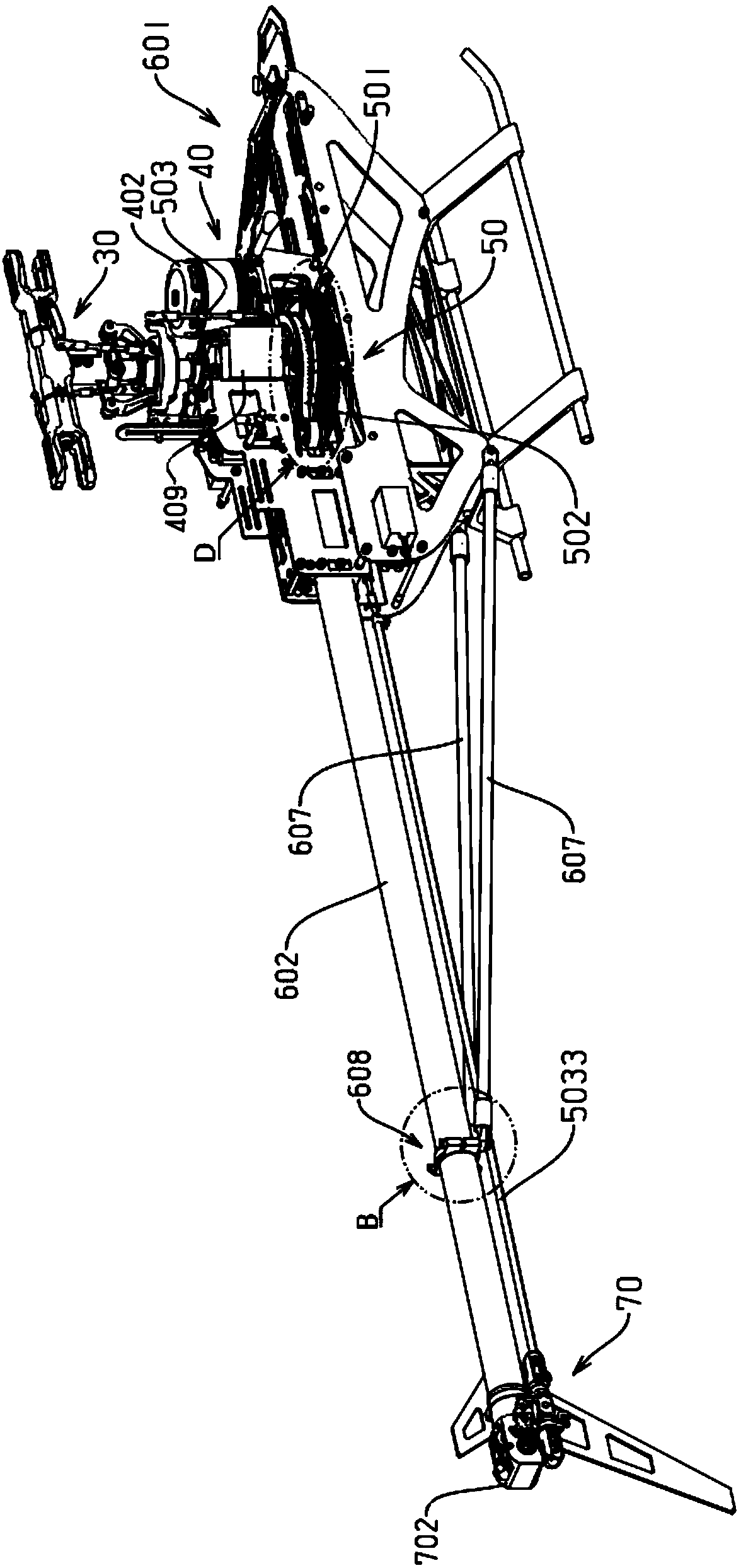
[0074] Embodiment: a kind of single-rotor UAV, such as figure 1 Shown: including UAV body and flight power system, the UAV body includes main body 601, tail pipe 602 and wake box 702, one end of the tail pipe is connected to the main body and the other end is connected to Wake box, the flight power system includes a rotor mechanism and a drive system, the rotor mechanism is connected to the drive system, the rotation and deflection of the rotor mechanism are driven by the drive system, and the rotor mechanism includes a main rotor mechanism 30 and an empennage mechanism 70, the main rotor mechanism is located at the main fuselage, and the empennage mechanism is located at the wake box;

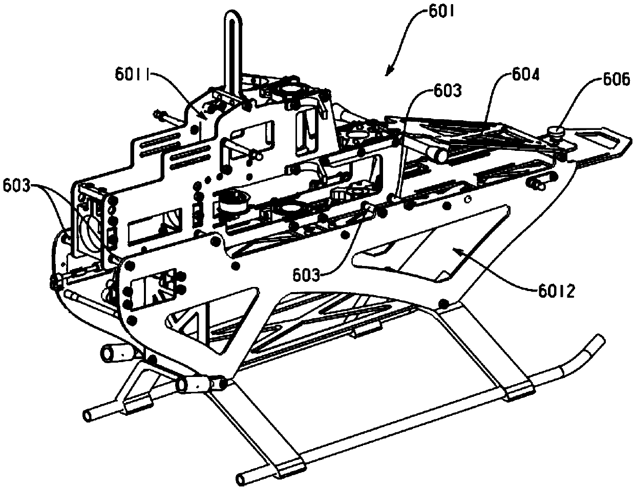
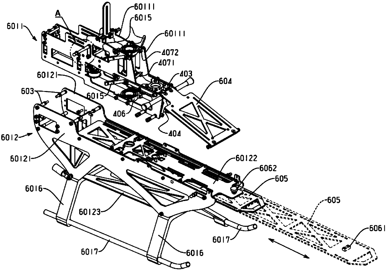
[0075] Such as figure 2 As shown: the main body includes a power bin 6011 and a power bin 6012 for placing batteries, the power bin is located above the power bin, and the power bin is connected to the power bin through studs 603, the A fuselage reinforcement plate 604 is provided between t...


PUM


Abstract

The invention discloses a single rotor wing unmanned aerial vehicle which comprises an unmanned aerial vehicle body and a flight power system. The unmanned aerial vehicle body comprises a main vehiclebody, a tail pipe and a tail wave box. The main vehicle body comprises a power cabin and a power supply cabin for placing a battery. The flight power system comprises a rotor wing mechanism and a driving system. The driving system comprises a driving unit and a transmission mechanism. The transmission mechanism comprises a gear transmission mechanism, a belt transmission mechanism and a connecting rod transmission mechanism. The axial play problem of the rotor wing mechanism and a spindle is solved by an angular contact bearing, stable transmission can be ensured while changing the transmission direction through belt transmission, a control slide block mechanism of an empennage is of quickly detachable bulb connection and locking connection, a tail supporting rod is connected to the tailpipe and the main vehicle body through a bulb, a body reinforcing plate is arranged between the power cabin and the power supply cabin, a hood fixing column is mounted through a fixed plate, and thesestructures are used for protecting parts effectively when the unmanned aerial vehicle falls off.

Description

technical field [0001] The invention belongs to the technical field of unmanned aerial vehicles, in particular to a single-rotor unmanned aerial vehicle. Background technique [0002] Single-rotor drones, also known as helicopter drones, fly through the main rotor and change the direction of deflection through the tail rotor. Compared with multi-rotor or fixed-wing drones, they have the characteristics of strong maneuverability and fast flight speed. , so in the field of competition, helicopter UAV has always been a relatively popular model, and the main rotor mechanism of helicopter UAV is the power source of the whole UAV, so the main rotor mechanism needs excellent stability for To ensure the stable flight of the UAV, when the main rotor rotates, due to the large centrifugal force, the deflection of the main rotor may not be completed smoothly, or the deflection cannot reach the predetermined angle. The main rotor mechanism of the existing helicopter UAV, its main The de...

Claims


Application Information

Patent Timeline
Patent Type & Authority Applications(China)
IPC IPC(8): B64D35/08B64D35/02B64C27/52B64C13/00B64C13/50B64C5/06B64C5/10
CPCB64D35/08B64C5/06B64C5/10B64C13/00B64C13/50B64C27/52B64D35/02
Inventor 罗佳文
Owner SUZHOU LINGSU ELECTRONICS TECH CO LTD
Learn More