
Main rotary wing system of single rotary wing UAV (Unmanned Aerial Vehicle)

A main rotor and UAV technology, applied in the field of UAV, can solve the problems of deflection and rotation set value error, deflection can not reach the predetermined angle, thrust bearing axial clearance is large, etc., to improve accuracy and rigidity Big, smooth flipping effects

Inactive Publication Date: 2019-01-01
SUZHOU LINGSU ELECTRONICS TECH CO LTD
View PDF0 Cites 2 Cited by
  • Summary
  • Abstract
  • Description
  • Claims
  • Application Information

AI Technical Summary

Problems solved by technology

[0002] Single-rotor drones, also known as helicopter drones, fly through the main rotor and change the direction of deflection through the tail rotor. Compared with multi-rotor or fixed-wing drones, they have the characteristics of strong maneuverability and fast flight speed. , so in the field of competition, helicopter drones have always been relatively popular models, and the main rotor mechanism of helicopter drones is the power source of the entire drone, so the main rotor mechanism needs excellent stability for To ensure the stable flight of the UAV, when the main rotor rotates, due to the large centrifugal force, the deflection of the main rotor may not be completed smoothly, or the deflection cannot reach the predetermined angle. The main rotor mechanism of the existing helicopter UAV, its main The deflection connection of the propeller clamp is completed by installing thrust bearings and ordinary roller bearings. The thrust bearing bears its centrifugal force. However, due to the large axial clearance of the thrust bearing, in actual use, the deflection and rotation of the main rotor are related to There is a certain error in the set value, so a main rotor mechanism that can effectively reduce the error caused by the centrifugal force and ensure a smoother deflection of the main rotor is needed;
[0003] In addition, since the driving motor of the drone needs to generate a huge torque, the fixing of the driving motor requires high stability. The output shaft of the existing driving motor and the main gear are suspended, that is, the output shaft protrudes. There is no mounting seat for fixing at the end. At this time, when the driving motor is running, its output shaft will vibrate, making it not tightly meshed with the driven toothed disc, and in severe cases, the phenomenon of tooth beating will occur. In addition, the rotor will It will generate high heat, so the heat dissipation of the drive motor is also very important

Method used


Image

  • Main rotary wing system of single rotary wing UAV (Unmanned Aerial Vehicle)
  • Main rotary wing system of single rotary wing UAV (Unmanned Aerial Vehicle)
  • Main rotary wing system of single rotary wing UAV (Unmanned Aerial Vehicle)

Examples


Embodiment

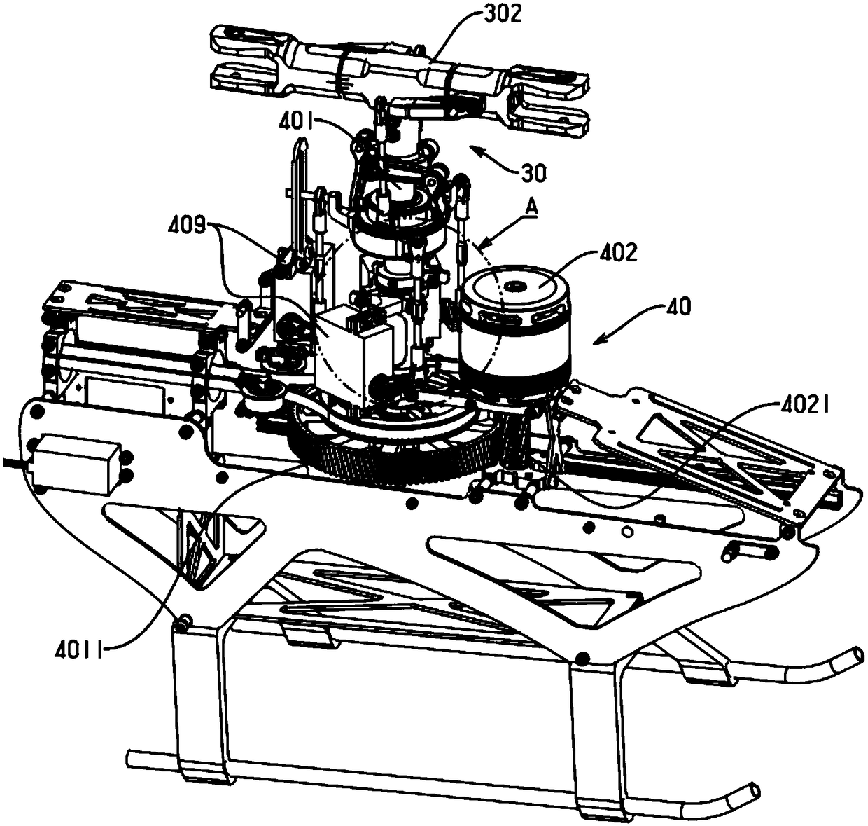
[0050] Embodiment: the main rotor system of a kind of single-rotor unmanned aerial vehicle, as figure 1 Shown: comprising a main rotor mechanism 30 and a drive system 40 for driving said main rotor mechanism;

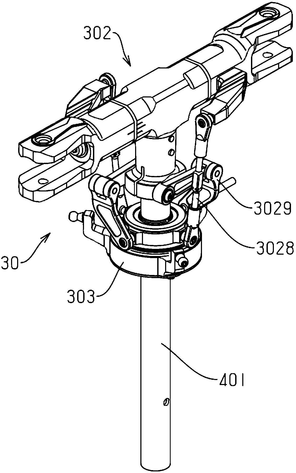
[0051] The main rotor mechanism includes a main rotor head 302 fixedly connected to the main shaft 401 of the drone, and the main rotor head is vertically arranged with the main shaft;

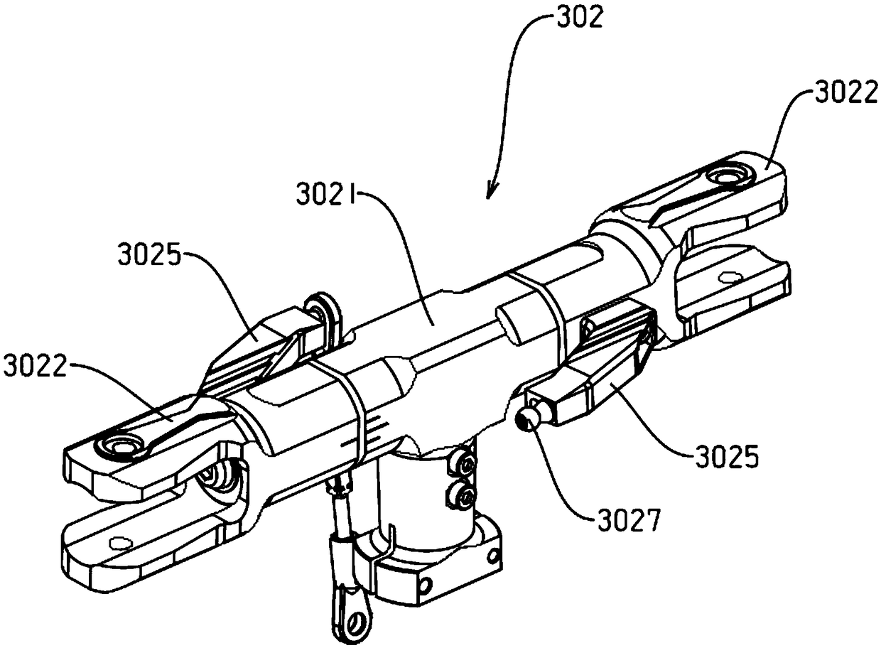
[0052] like figure 2 , image 3 and Figure 4 As shown: the main rotor head includes a central paddle seat 3021, the central paddle seat has a vertical arm 30211 and a cross arm 30212, and the central paddle seat is formed into a "T" shape by the cross arm and the vertical arm structure, the vertical arm is fixedly connected to the main shaft, and both ends of the cross arm are provided with a main blade clamp 3022 for clamping the main rotor, and one end of the main blade clamp is sleeved on the cross arm, and the Thrust bearing 3023 and at least one angular contact bearing 3024 a...


PUM


Abstract

The invention discloses a main rotary wing system of a single rotary wing UAV (Unmanned Aerial Vehicle). The main rotary wing system comprises a main rotary wing head fixedly connected with a main shaft of the UAV, wherein the main rotary wing head comprises a propeller middle connection part, the propeller middle connection part comprises a vertical arm and a transverse arm that form a T-shaped structure, the vertical arm is fixedly connected with the main shaft, two ends of the transverse arm are separately provided with a main propeller clamp clamping the main rotary wing, one end of the main propeller clamp is sleeved with the transverse arm, the sleeved part is provided with a pushing bearing and one or more angle contact bearing, the two main propeller clamps are rotatably connectedwith the transverse arm through the pushing bearing and the angle contact bearing, and side walls of the two main propeller clamps are separately provided with a propeller clamp arm. A problem of axial internal clearance of the main rotary wing is solved through the angle contact bearing, the main rotary wing can deflect more fluently while the main rotary wing is guaranteed not to creep axially,and the main rotary ring mechanism is guaranteed stable while the UAV runs.

Description

technical field [0001] The invention belongs to the technical field of unmanned aerial vehicles, in particular to a single-rotor unmanned aerial vehicle. Background technique [0002] Single-rotor drones, also known as helicopter drones, fly through the main rotor and change the direction of deflection through the tail rotor. Compared with multi-rotor or fixed-wing drones, they have the characteristics of strong maneuverability and fast flight speed. , so in the field of competition, helicopter UAV has always been a relatively popular model, and the main rotor mechanism of helicopter UAV is the power source of the whole UAV, so the main rotor mechanism needs excellent stability for To ensure the stable flight of the UAV, when the main rotor rotates, due to the large centrifugal force, the deflection of the main rotor may not be completed smoothly, or the deflection cannot reach the predetermined angle. The main rotor mechanism of the existing helicopter UAV, its main The de...

Claims


Application Information

Patent Timeline
Patent Type & Authority Applications(China)
IPC IPC(8): B64C27/06B64C27/32B64C27/59B64D33/10
CPCB64C27/06B64C27/32B64C27/59B64D33/10B64U50/19B64U30/20B64U10/10
Inventor 罗佳文
Owner SUZHOU LINGSU ELECTRONICS TECH CO LTD
Learn More