Eureka AIR delivers breakthrough ideas for toughest innovation challenges, trusted by R&D personnel around the world.

A Planar Ultrasonic Vibration Assisted Machining Platform

A technology of ultrasonic vibration and auxiliary processing, applied in the direction of fluid using vibration, can solve the problems of chip accumulation, slow marking speed, large normal force of processing, etc., and achieve high-precision frequency, controllable amplitude, and controllable frequency Effect

Inactive Publication Date: 2020-08-14
TIANJIN UNIV
View PDF5 Cites 0 Cited by
  • Summary
  • Abstract
  • Description
  • Claims
  • Application Information

AI Technical Summary

Problems solved by technology

However, the probe directly marks the surface of the sample - "plowing" processing, which has the inherent disadvantages of large processing normal force, easy accumulation of chips, and slow marking speed, and cannot directly mark high-hardness materials, viscoelastic materials, etc. Materials with special properties, such as materials, severely limit the application range of probe scribing
For this reason, various energy-assisted methods for probe scribing have been developed, including probe heating, electrochemical machining, vibration-assisted machining, etc. Among them, vibration-assisted machining has simple principles, strong material adaptability, and can be used in natural However, most existing ultrasonic vibration auxiliary platforms have shortcomings such as motion coupling and limited frequency.

Method used


Image

  • A Planar Ultrasonic Vibration Assisted Machining Platform
  • A Planar Ultrasonic Vibration Assisted Machining Platform

Examples


Embodiment Construction

[0018] A planar ultrasonic vibration assisted processing platform of the present invention will be described in detail below with reference to the embodiments and the accompanying drawings.

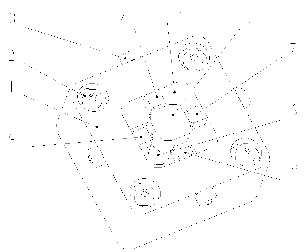
[0019] Such as figure 1 , figure 2 As shown, a plane ultrasonic vibration assisted processing platform of the present invention includes a rectangular base 1, a rectangular groove 10 is formed in the middle of the rectangular frame base 1, and the center of the rectangular groove 10 passes through a horizontally isotropic The decoupling pillar 6 made of material is provided with a moving platform 5 , the upper end of the decoupling pillar 6 is bonded to the moving platform 5 , and the lower end is fixedly connected to the inner bottom surface of the rectangular groove 10 . The transversely isotropic material is graphite or sedimentary rock, which decouples plane vibrations and eliminates coupling errors of ultrasonic vibrations in X / Y two working directions.

[0020] A piezoelectric ce...


PUM


Abstract

The invention discloses a plane supersonic vibration auxiliary machining platform. The plane supersonic vibration auxiliary machining platform comprises a rectangular base body. A rectangular groove is formed in the middle of the rectangular base body. A moving platform is arranged in the center of the rectangular groove through a decoupling support pillar, wherein the decoupling support pillar ismade of a transverse isotropy material. A piezoelectric ceramic driver is arranged between each of four inner side edges of the rectangular base body and the moving platform. The plane end of each piezoelectric ceramic driver is in surface contact connection with the corresponding inner side edge of the rectangular base body. The arc-surface end of each piezoelectric ceramic driver is in point connection with the moving platform. Pre-tightening bolts are arranged at the positions, corresponding to the piezoelectric ceramic drivers, of the four edges of the rectangular base body, wherein the pre-tightening bolts are in threaded connection and penetrate the edges. The pre-tightening bolts are used for conducting adjustive pre-tightening on contact connection between the moving platform andthe piezoelectric ceramic drivers. By means of the plane supersonic vibration auxiliary machining platform, a whole system can achieve sufficient rigidity and stability and the high-precision and high-reliabilty supersonic vibration auxiliary functions with the controllable amplitude and frequency.

Description

technical field [0001] The invention relates to a processing platform. In particular, it relates to a planar ultrasonic vibration assisted processing platform. Background technique [0002] Micro-nano scribing processing technology based on scanning probe has been more and more widely used in micro-nano scale processing due to its simple structure, low cost, high precision, and ability to scribe arbitrary patterns. However, the probe directly marks the surface of the sample - "plowing" processing, which has the inherent disadvantages of large processing normal force, easy accumulation of chips, and slow marking speed, and cannot directly mark high-hardness materials, viscoelastic materials, etc. Materials with special properties, such as materials, severely limit the scope of application of probe scribing. For this reason, various energy-assisted methods for probe scribing have been researched, including probe heating, electrochemical machining, vibration-assisted machinin...

Claims


Application Information

Patent Timeline
Patent Type & Authority Patents(China)
IPC IPC(8): B06B1/06
CPCB06B1/06
Inventor 卢康康田延岭王福军周重凯张大卫
Owner TIANJIN UNIV
Why Eureka
Eureka Blog
Learn More