Eureka AIR delivers breakthrough ideas for toughest innovation challenges, trusted by R&D personnel around the world.

Thin-walled tube penetrating and conveying device

A technology for conveying devices and thin-walled pipes, which is applied in the field of thin-walled pipe-through-pipe conveying devices, which can solve problems such as simple and boring work for workers, unavoidable damage, and damage to thin-walled pipe fittings, so as to improve the working environment of workers and avoid jamming damage and avoid bending damage

Pending Publication Date: 2019-04-23
郑州科慧科技股份有限公司
View PDF7 Cites 5 Cited by
  • Summary
  • Abstract
  • Description
  • Claims
  • Application Information

AI Technical Summary

Problems solved by technology

Causes the problems of slow penetration speed, simple and boring work for workers, high labor intensity and long production cycle
In addition, in the process of perforating and conveying thin-walled pipe fittings, if there is a blockage in the front, the thin-walled pipe cannot continue to move forward, and the mechanism continues to transport, which will cause damage to the thin-walled pipe fittings, and the pipe fittings will be conveyed very quickly. Detection cannot avoid damage due to action time lag

Method used


Image

  • Thin-walled tube penetrating and conveying device
  • Thin-walled tube penetrating and conveying device
  • Thin-walled tube penetrating and conveying device

Examples


Embodiment

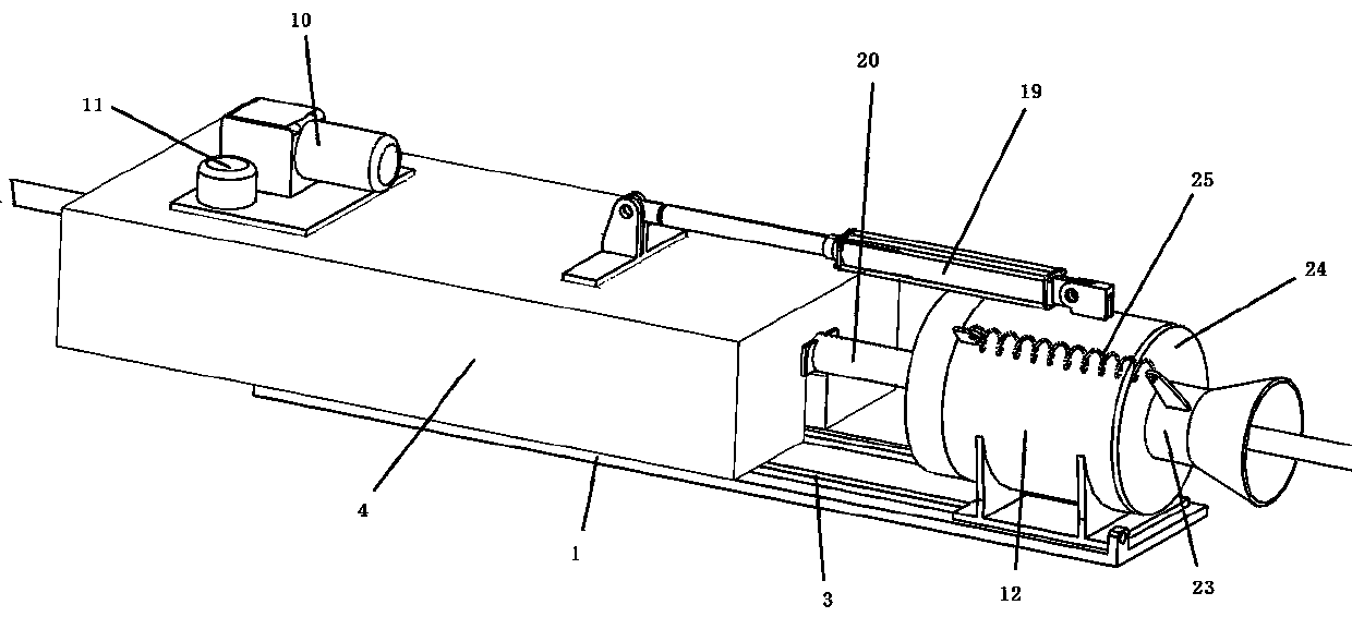
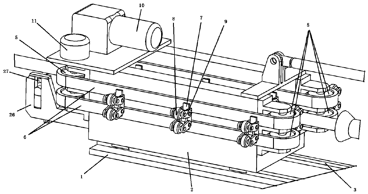
[0025] Such as Figure 1 to Figure 7 As shown, a thin-walled pipe piercing conveying device includes an installation base 1, a slide table 2 is provided on the left side above the installation base, a slide rail 3 is provided on the upper surface of the installation base 1, and the slide table 2 A slide groove is arranged on the lower bottom surface, and the slide groove is arranged on the slide rail 3, so relative sliding can occur between the installation base 1 and the slide table. A shield 4 is provided above the slide 2, and the left and right ends of the shield 4 are provided with inlets and outlets for thin-walled pipes. The slide 2 and the shield 4 are fixedly connected, that is, the slide 2 and the shield There will be no relative displacement between 4. The slide table 2 is provided with two groups of clamping and conveying mechanisms opposite to each other, and each set of clamping and conveying mechanisms includes sprockets 5 arranged at the left and right ends of...


PUM


Abstract

The invention belongs to the field of equipment for producing boilers, and relates to a thin-walled tube penetrating and conveying device, which is applied to the installation of thin-walled tubes inheat exchangers of boilers. The thin-walled tube penetrating and conveying device comprises a mounting base, wherein a sliding table is arranged on one side above the mounting base, relative sliding can occur between the mounting base and the sliding table, a protective cover is arranged above the sliding table, an inlet and an outlet are formed in the left and right ends of the protective cover,the sliding table is fixedly connected with the protective cover, two groups of clamping and conveying mechanisms which are opposite to each other are arranged on the sliding table, a sleeve which isfixedly connected is arranged on the other side of the mounting base, a holding ring and a guide ring are arranged in one end of the sleeve, the holding ring is connected with the sleeve, a four-linkage mechanism is arranged between the holding ring and the guide ring, an air cylinder is arranged between the protective cover and the sleeve, and a pressing mechanism is arranged between the guide ring and the protective cover. The continuous conveying of the thin-walled tubes is realized without damage, the automatic conveying of the thin-walled tubes is realized, the work environment of workersis greatly improved, and the working efficiency is improved.

Description

technical field [0001] The invention belongs to the field of equipment for producing boilers, and in particular relates to a thin-walled pipe-through-pipe conveying device used for installing thin-walled pipes in boiler heat exchangers. Background technique [0002] Among the boiler accessories, the exchanger is an important core accessory. The thin-walled tube in the exchanger is an important heat exchange component. The thin-walled or slender round tube has low rigidity, poor stiffness, and is difficult to clamp and center. Bending damage occurs, and the thin-walled tubes in the exchanger industry cannot withstand large clamping forces due to their thin-walled characteristics, and manual operations are still used during the transportation process. Causes the problems of slow penetration speed, simple and boring work of workers, high labor intensity and long production cycle. In addition, in the process of perforating and conveying thin-walled pipe fittings, if there is a ...

Claims


Application Information

Patent Timeline
Patent Type & Authority Applications(China)
IPC IPC(8): B65G13/06B65G13/00
CPCB65G13/00B65G13/06B65G2201/0276
Inventor 康治政陈志宏杨爱国贾玉涛
Owner 郑州科慧科技股份有限公司
Why Eureka
Eureka Blog
Learn More