
Size design method of a large thin-wall ball valve

A ball valve, thin-walled technology, applied in the field of size design of large thin-walled ball valves, can solve the problems of increasing production cycle and cost, increasing production cost, reducing machining allowance, etc., so as to improve production cycle, avoid repair processing, reduce The effect of processing time

Active Publication Date: 2019-04-19
KOCEL STEEL
View PDF2 Cites 2 Cited by
  • Summary
  • Abstract
  • Description
  • Claims
  • Application Information

AI Technical Summary

Problems solved by technology

[0004]1. The area of ​​the outer spherical surface of the casting near the middle parting surface is large and large, seriously exceeding the standard tolerance requirements, and a large number of gouging repairs are required to make the outer wall size meet the standard requirements, increasing Production cycle and cost;
[0005]2. The lack of the inner spherical surface of the casting near the middle parting surface seriously exceeds the standard tolerance requirements. Corrective heat treatment or large-area welding repair is required to make the inner wall of the casting meet the Standard tolerance requirements increase production cycle and cost;
[0006]3. The machining allowance of the arc top of the inner circular surface of the casting becomes larger, and the machining allowance on both sides becomes smaller or has no machining allowance. It needs to be further improved through subsequent processing. If it cannot be improved, the casting will be scrapped and the production cost will be increased

Method used


Image

  • Size design method of a large thin-wall ball valve
  • Size design method of a large thin-wall ball valve

Examples


Embodiment Construction

[0040] The implementation of the present invention will be described below through specific examples in conjunction with the accompanying drawings, and those skilled in the art can easily understand other advantages and effects of the present invention from the content disclosed in this specification. The present invention can also be implemented or applied through other different specific implementation modes, and various modifications or changes can be made to the details in this specification based on different viewpoints and applications without departing from the spirit of the present invention.

[0041] It should be noted that the structures, proportions, sizes, etc. shown in the drawings attached to this specification are only used to match the content disclosed in the specification, for those who are familiar with this technology to understand and read, and are not intended to limit the present invention Therefore, it has no technical substantive meaning, and any modifi...


PUM


Abstract

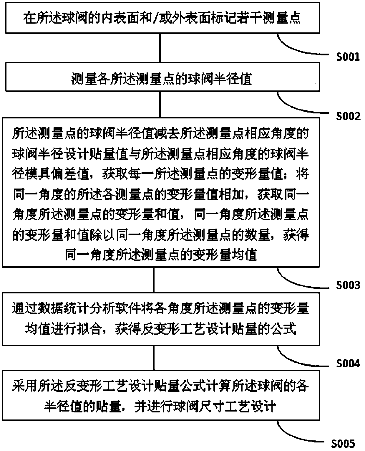
The invention belongs to the technical field of casting, and relates to a size design method of a large thin-wall ball valve, which comprises the following steps of: marking a plurality of measuring points on the inner surface and / or the outer surface of the ball valve; Measuring the ball valve radius value of each measuring point; Subtracting the ball valve radius design sticking value of the corresponding angle measuring point from the ball valve radius value of the measuring point and the ball valve radius mold deviation value of the measuring point to obtain a deformation value; Adding thedeformation values to obtain the deformation sum value of the same angle measurement point, and dividing the deformation sum value of the same angle measurement point by the number of the same anglemeasurement points to obtain a deformation mean value of the same angle measurement point; Fitting the mean value of the deformation amounts of the angle measurement points through data statistical analysis software to obtain a formula of the anti-deformation process design sticking amount; According to the method, the sticking amount of each radius value of the ball valve is calculated by adopting a sticking amount formula designed by adopting a reverse deformation process, and the size process design of the ball valve is performed, so that the production period is remarkably prolonged and the cost is saved through the reverse deformation size process design of the method.

Description

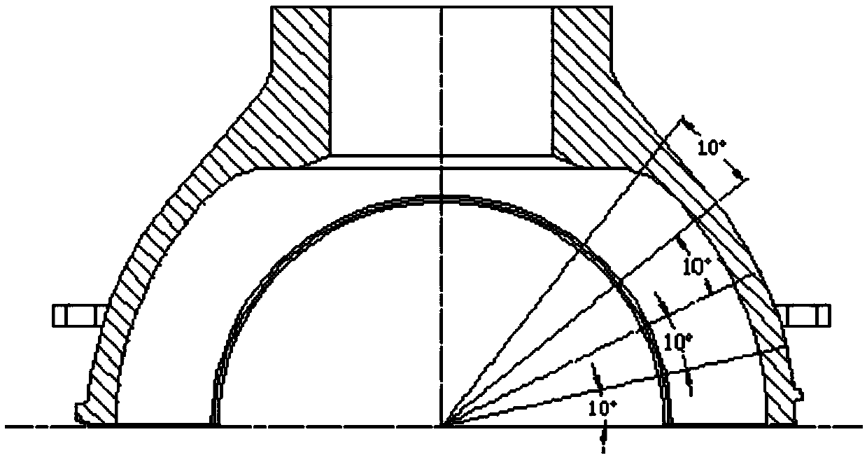
technical field [0001] The invention belongs to the technical field of casting, and mainly relates to a size design method of a large thin-walled ball valve. Background technique [0002] The large ball valve casting structure is a hemispherical C-shaped structure, the general diameter range is 2800mm-5000mm, the spherical wall thickness range is 80mm-150mm, and the wall thickness is relatively thin. The dimensional tolerance standard of the casting requires CT12-CT14. Tolerance requirements are higher and, for sand casting dimensional requirements, very stringent. Since the casting structure of the ball valve casting is C-shaped, there is deformation during the casting process and the mass heat treatment process, and the main deformation trend is opening. [0003] In the prior art, when designing the size process of large ball valve castings, according to the tolerance requirements for the inner and outer spherical surfaces of the castings according to the drawings, the ov...

Claims


Application Information

Patent Timeline
Patent Type & Authority Applications(China)
IPC IPC(8): G06F17/50
CPCG06F30/17G06F30/20
Inventor 马金鑫郭小利苏志东郭小强马斌冯周荣唐钟雪李阳马文治
Owner KOCEL STEEL
Learn More