
A rapid cooling device for chemical materials

A rapid cooling and material technology, used in household refrigeration devices, lighting and heating equipment, household appliances, etc., can solve the problems of low cooling and cooling efficiency, insufficient material cooling, etc., to achieve fast cooling speed, full and fast turning effect. cooling effect

Active Publication Date: 2020-12-01
JIANGXI GUOHUA IND CO LTD
View PDF6 Cites 0 Cited by
  • Summary
  • Abstract
  • Description
  • Claims
  • Application Information

AI Technical Summary

Problems solved by technology

[0003] In the process of chemical production, chemical materials need to be cooled according to the actual needs of process production, but the cooling efficiency of the current cooling device is low, and the cooling of materials is not sufficient enough to meet the current production requirements. Therefore, now A chemical material rapid cooling device is provided to solve the above technical problems

Method used


Image

  • A rapid cooling device for chemical materials
  • A rapid cooling device for chemical materials
  • A rapid cooling device for chemical materials

Examples


Embodiment 1

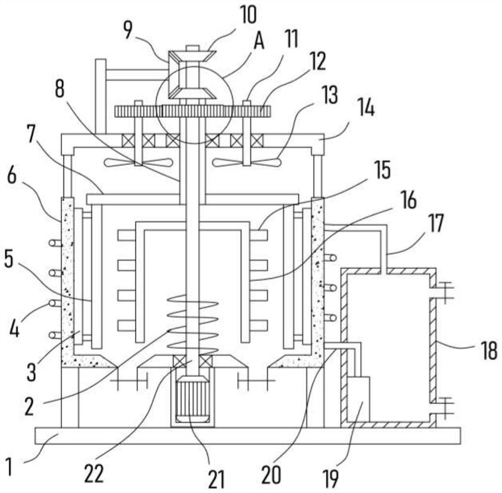
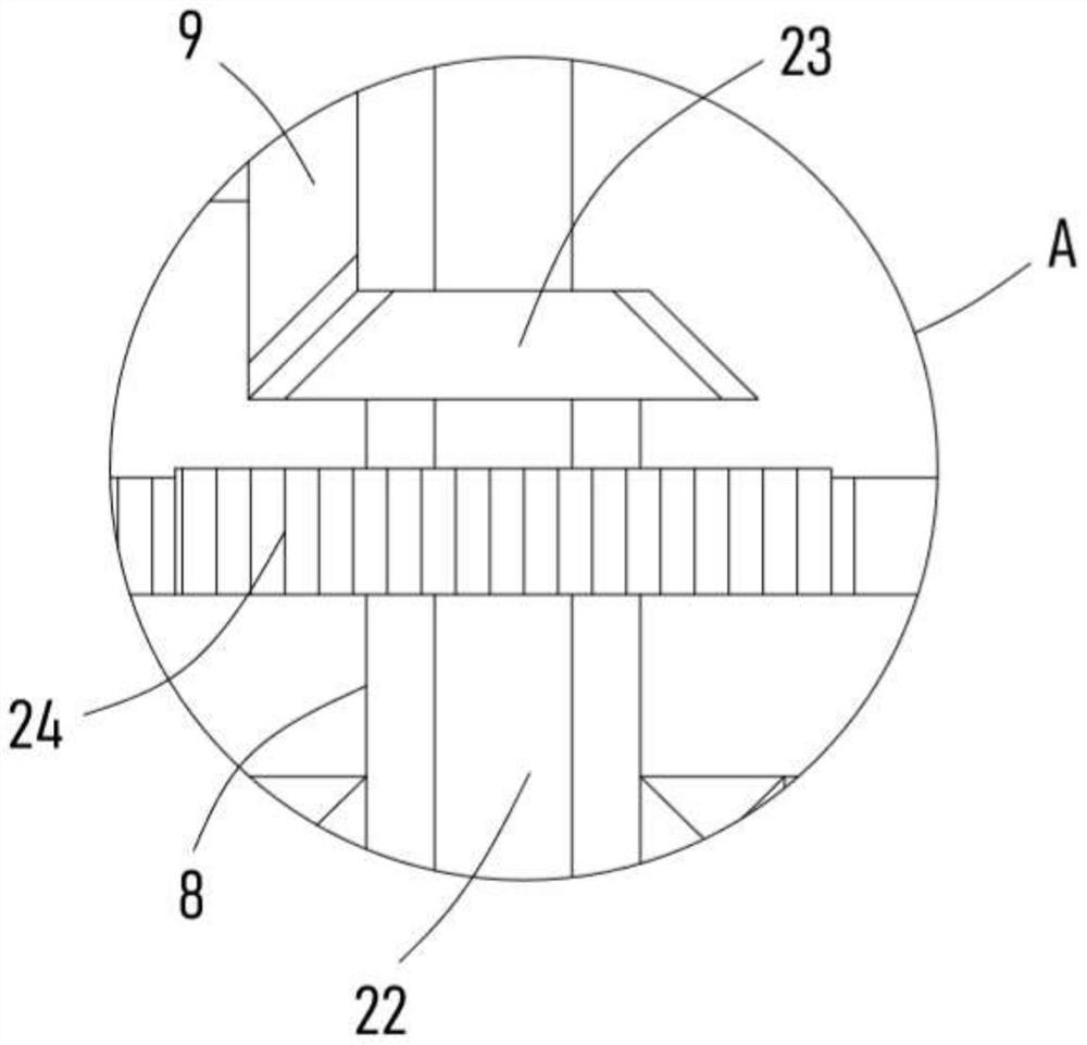
[0021] see Figure 1-3 , a chemical material rapid cooling device, comprising a support plate 1, a cooling barrel 6 is fixedly installed on the support plate 1, the cooling barrel 6 is an open structure, and the cooling barrel 6 is used to store the chemical materials to be cooled, and the cooling The barrel 6 is fixed with a fixed frame 14, the support plate 1 is fixedly installed with a drive motor 21, the output shaft of the drive motor 21 is coaxially fixed with a drive shaft 22 extending into the cooling barrel 6, and the side wall of the drive shaft 22 is fixed. The inner frame 16 is evenly fixed with several stirring teeth 15 on the inner frame 16 .

[0022] The drive motor 21 drives the drive shaft 22 to rotate, and the drive shaft 22 drives the inner frame 16 to rotate to realize the stirring of the chemical raw materials in the cooling barrel 6, and the fixed stirring teeth 15 on the inner frame 16 can further promote the chemical raw materials as the inner frame 16 ...

Embodiment 2

[0028] On the basis of Embodiment 1, in addition, the scraper 3 abutting against the inner wall of the cooling barrel 6 is fixedly installed on the side of the stirring rod 5 close to the inner wall of the cooling barrel 6, and the rotation of the stirring rod 5 drives the stirring rod 5 to the cooling barrel 6. The inner wall is scraped, which makes the mixing range of chemical materials wider and the heat dissipation effect is more sufficient.

[0029] Further, the surface of the driving shaft 22 is fixed with a screw blade 2, and the screw blade 2 is located inside the cooling barrel 6. The screw blade 2 is set to rotate with the driving shaft 22 and the chemical raw materials at the bottom of the cooling barrel 6 are spirally turned upwards, so that the chemical materials The heat dissipation effect is better.

[0030] Further, a cold water tank 18 located on one side of the cooling bucket 6 is fixedly installed on the support plate 1, and the cold water tank 18 is filled ...


PUM


Abstract

The invention discloses a quick cooling device for chemical materials, and relates to the technical field of chemical devices. The quick cooling device comprises a supporting plate, wherein a coolingbarrel is fixedly mounted on the supporting plate; a fixed frame is fixedly erected on the cooling barrel; the output shaft of a drive motor is coaxially fixed with a drive shaft which extends into the cooling barrel; a secondary gear which is engaged with a primary gear is fixedly arranged on a driven shaft in a sleeving mode; and fan blades are fixedly mounted on the side wall of the driven shaft. According to the quick cooling device disclosed by the invention, an outer frame drives a stirring rod and an inner frame reversely rotates to realize sufficient stirring effect on chemical materials in the cooling barrel, so that the material turnover effect is more sufficient, and dissipation of heat is greatly promoted; the fan blades rotate along with the driven shaft and blow air into thecooling barrel, so that flow of air is promoted, and a heat removal rate is increased; cold water capable of being circulated is led into a spiral ring tube, so that the cooling effect of the coolingbarrel is realized; and a heat dissipation way combining convection and heat conduction is used to realize the quick cooling effect on chemical materials, so that the cooling speed is high, and cooling is more complete.

Description

technical field [0001] The invention relates to the technical field of chemical equipment, in particular to a rapid cooling device for chemical materials. Background technique [0002] Chemical industry is the abbreviation of "chemical technology", "chemical industry", "chemical engineering" and so on. Any technology that uses chemical methods to change the composition and structure of substances or to synthesize new substances belongs to chemical production technology, that is, chemical technology, and the resulting products are called chemicals or chemical products. At first, what produce this series products is handicraft workshop, develops into factory later, and has gradually formed specific production industry, namely a chemical industry. Chemical engineering is a science that studies the general laws of the production process of chemical products. The relationship between human beings and chemical industry is very close. Some chemical products play an epoch-making r...

Claims


Application Information

Patent Timeline
Patent Type & Authority Patents(China)
IPC IPC(8): F25D1/00
CPCF25D1/00
Inventor 高美珍
Owner JIANGXI GUOHUA IND CO LTD
Learn More