
Wind and wave energy combined power generation device based on guide tube frame foundation

A technology for combined power generation and power generation devices, which is applied in wind power generation, ocean power generation, and the combination of wind power generators and water power converters. problems, to achieve the effects of high economy and structural safety, excellent structural stability, and improved power generation efficiency

Pending Publication Date: 2019-04-19
CHANGJIANG SURVEY PLANNING DESIGN & RES
View PDF0 Cites 3 Cited by
  • Summary
  • Abstract
  • Description
  • Claims
  • Application Information

AI Technical Summary

Problems solved by technology

[0003] Wave energy and offshore wind energy are also renewable clean energy with huge reserves. The difference between them and offshore wind energy is that the existing wave energy power generation devices have the defects of less energy absorption, low conversion rate, high cost and high damage rate. The bottleneck of wave energy has led to the fact that wave energy does not yet have the value of large-scale development. Most of the wave energy power generation devices launched by scientific research institutes and enterprises on the sea are single-point launch, which are only used for scientific research and teaching, and do not have the conditions for grid-connected power generation.
[0004] Aiming at the defects of low conversion rate of wave energy generation device, high cost of support structure, and easy to be corroded by seawater, with the help of the stable support structure of offshore wind power and the coexistence of offshore wind power and wave energy, a joint offshore wind energy and wave energy based on support structure is studied. The power generation device is of positive significance to reduce the cost, improve the power generation efficiency, and realize the commercialization of wave energy development

Method used


Image

  • Wind and wave energy combined power generation device based on guide tube frame foundation
  • Wind and wave energy combined power generation device based on guide tube frame foundation

Examples


Embodiment Construction

[0018] The present invention will be further described below in conjunction with the accompanying drawings and specific embodiments.

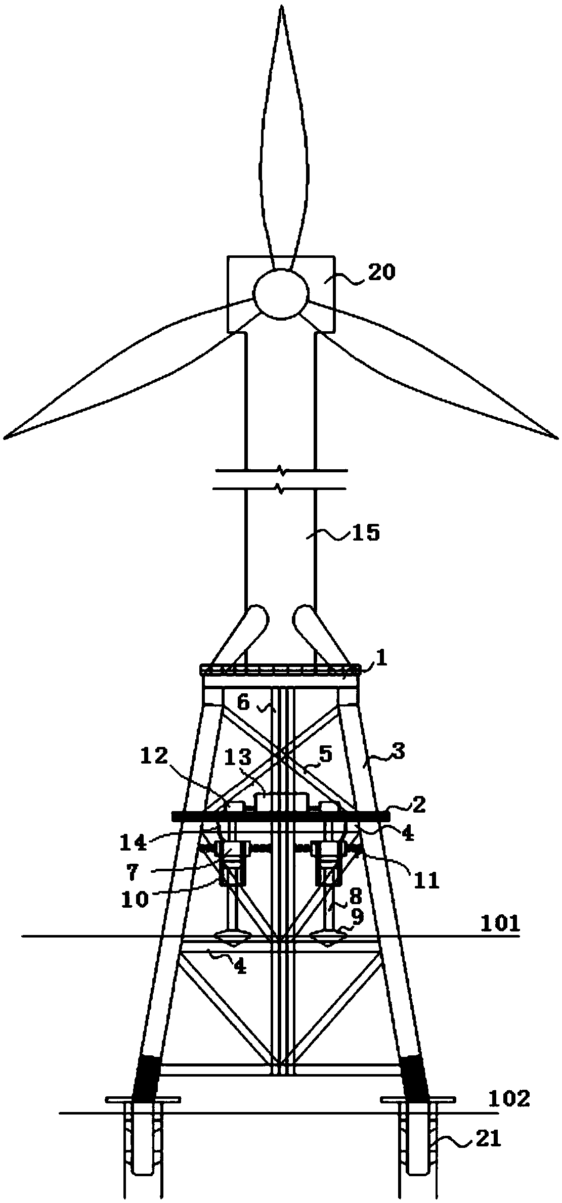
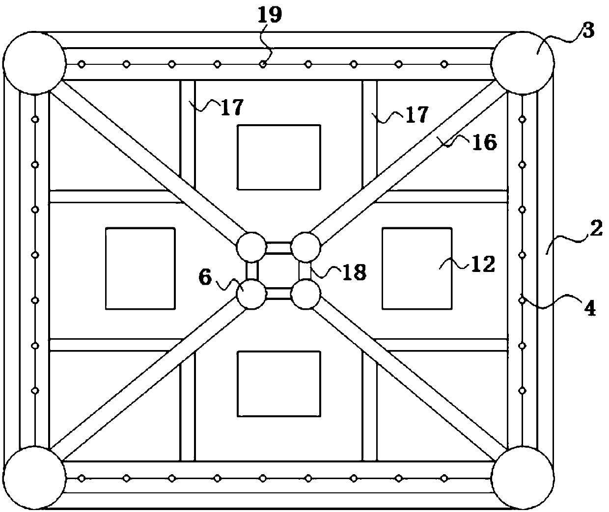
[0019] like Figure 1-2 As shown, a wind energy and wave energy combined power generation device based on a jacket foundation of the present invention includes main pile legs 21, a jacket foundation, a wind power generation platform 1, a wind power generation device, a wave power generation platform 2 and a wave power generation device , the main leg 21 is fixed below the mud surface line 102, and the bottom of the jacket foundation is fixed to the main leg 21 as the bearing foundation of the entire combined power generation device. The top of the jacket foundation is provided with a wind power generation platform 1, and the wind power generation device is fixed On the wind power generation platform 1 , in this embodiment, the wind power generation device adopts a wind turbine 20 .

[0020] The wave energy generation platform 2 is fixedly inst...


PUM


Abstract

The invention relates to a wind and wave energy combined power generation device based on a guide tube frame foundation. The combined power generation device comprises a main pile leg, the guide tubeframe foundation, a wind energy power generation platform, a wind power generation device, a wave energy power generation platform and a wave energy power generation device, wherein the wave energy power generation platform is arranged above the water, and a floater of the wave energy power generation device floats on the water. The guide tube frame foundation is used as a support structure, and aguide tube frame has excellent structural stability and is used as the support structure of a wind driven generator and a wave driven generator, so that the utilization rate of the guide tube frame foundation is increased, the problems of high cost of the support structure of the wave energy power generation device and low economic benefit of single power generation are solved, the overall generation efficiency is improved, and the effect of high feasibility is achieved on economy and structural safety.

Description

technical field [0001] The invention relates to the technical field of offshore wind turbine foundations, in particular to a wind energy and wave energy combined power generation device based on a jacket foundation. Background technique [0002] With the continuation of the world's energy crisis and the destruction of the environment by fossil energy consumption, human demand for renewable clean energy is increasing. The exploration and research of renewable clean energy has gradually extended from land to the vast ocean. Offshore wind energy is currently the most It is one of the clean energy with commercial development value and the most mature technology. It has the characteristics of abundant reserves, stable and continuous power generation, and high hours of power generation. It is suitable for large-scale development. According to incomplete statistics, my country's offshore wind energy reserves exceed 700 million kilowatts. Estimated development value. Offshore wind po...

Claims


Application Information

Patent Timeline
Patent Type & Authority Applications(China)
IPC IPC(8): F03D13/25F03D9/25F03B13/18
CPCF03B13/187F03D9/008F03D9/25F03D13/25Y02E10/727Y02E10/30Y02E10/72
Inventor 曾斌程卫民陶铁铃邹尤赵鑫曹龙喻飞李宇飞汪顺吉金乾
Owner CHANGJIANG SURVEY PLANNING DESIGN & RES
Learn More