Device and method for enabling thickness of retainer locking claw to be consistent
A technology for cages and locking claws, applied in feeding devices, metal processing, automatic control devices, etc., can solve the problem of inconsistent thickness on both sides of the locking claws, and achieve the effect of saving material costs and improving work efficiency
- Summary
- Abstract
- Description
- Claims
- Application Information
AI Technical Summary
Problems solved by technology
Method used
Image
Examples
specific Embodiment approach 1
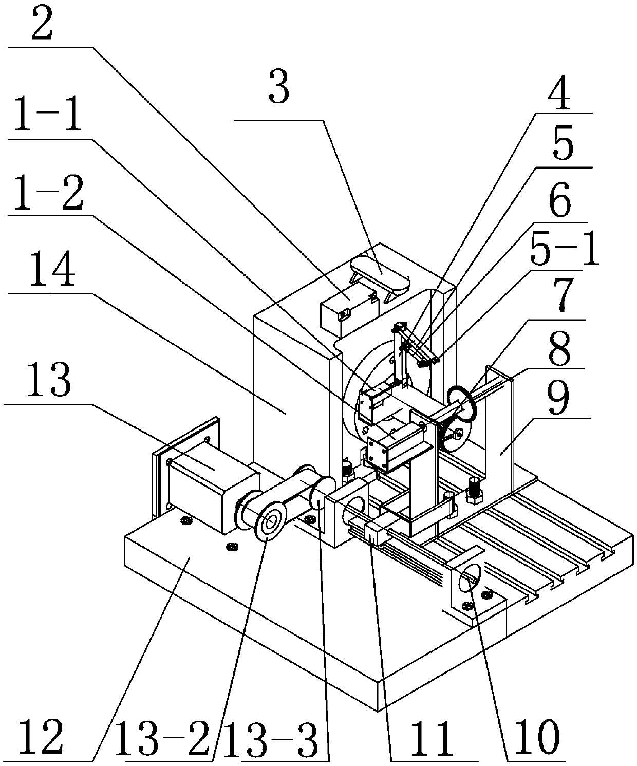
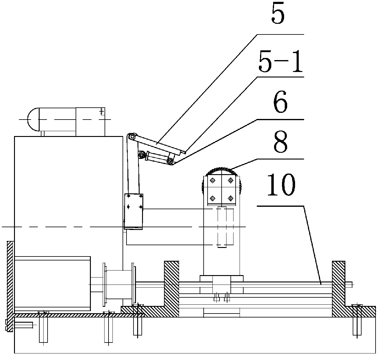
[0024] Specific Embodiment 1: A device for making the thickness of the cage lock claw consistent, including No. 2 control motor 1-2, No. 1 motor frame 1-3, No. 2 motor frame 1-4, power supply 2, cage 7, Tool 8, base 12, machine base 14, No. 1 control motor 1-1, air pump 3, No. 1 mechanical arm 4, No. 2 mechanical arm 5, alignment mechanism 5-1, telescopic cylinder 6 and knife rod 9;
[0025] The base 14 is arranged on the upper end surface of the base 12 and is fixedly connected with the base 12. The upper end surface of the base 14 is provided with a power supply 2 and an air pump 3. The front end of the base 14 is provided with a cylinder, and one end of the cylinder Fixedly connected with the base 14, the side of one end of the cylinder is provided with a No. 1 motor frame 1-3, and the No. 1 control motor 1-1 is fixedly connected with the No. 1 motor frame 1-3 by screws, and the No. 1 control motor 1-3 is fixedly connected with the No. 1 motor frame 1-3 by screws. 1 is conn...
specific Embodiment approach 2
[0028] Specific embodiment 2: The difference between this embodiment and specific embodiment 1 is: a device that makes the thickness of the locking claw of the cage consistent, and also includes a screw 10, a screw arm 11, a control motor 13 on the 3rd, and a transmission belt 13- 1. The driving wheel 13-2 and the driven wheel 13-3. The other side of the base 12 is provided with a No. 3 control motor 13. The No. 3 control motor 13 is positioned and connected with the driving wheel 13-2 through a transmission shaft. The driving wheel 13- 2. Connect the driven wheel 13-3 through the transmission belt 13-1, and the driven wheel 13-3 is positioned and connected with one end of the lead screw 10. One end of the lead screw arm 11 is provided with a threaded through hole in the axial direction, and the other end of the lead screw 10 is connected to the screw. The threaded through hole of the screw arm 11 is threadedly connected, and the other end of the screw arm 11 is provided with t...
specific Embodiment approach 3
[0030] Specific embodiment three: the difference between this embodiment and specific embodiment one or two is that: the inside of the through hole at one end of the No. 1 mechanical arm 4 is provided with a keyway, and is provided with a positioning key, and No. 1 is controlled by the positioning key. The transmission shaft of the motor 1-1 is positioned and connected to one end of the No. 1 mechanical arm 4, which limits the degree of freedom of the No. 1 mechanical arm 4 and the transmission shaft along the axis of the circumference.
PUM
 Abstract
Description
Claims
Application Information
 - R&D
- Intellectual Property
- Life Sciences
- Materials
- Tech Scout
- Unparalleled Data Quality
- Higher Quality Content
- 60% Fewer Hallucinations
Browse by: Latest US Patents, China's latest patents, Technical Efficacy Thesaurus, Application Domain, Technology Topic, Popular Technical Reports.
© 2025 PatSnap. All rights reserved.Legal|Privacy policy|Modern Slavery Act Transparency Statement|Sitemap|About US| Contact US: help@patsnap.com


