Efficient cutting mechanism for linear guide rail

A linear guide rail and cutting mechanism technology, applied in the direction of shearing devices, shearing equipment, metal processing equipment, etc., can solve the problems of low surface quality of the incision, movement of the rotating shaft, prolonged contact time, etc., and achieve motion stability and moving straight line Good precision, smooth and precise cutting, improving the effect of high temperature problems

Inactive Publication Date: 2019-04-19
浙江鹏银科技发展有限公司
View PDF7 Cites 0 Cited by
  • Summary
  • Abstract
  • Description
  • Claims
  • Application Information

AI Technical Summary

Problems solved by technology

[0003] In the process of linear guide rail processing, it is often necessary to cut to a fixed length according to the designed length; the existing technology uses a traditional cutting machine for cutting, and the cutting piece of the cutting machine rotates at high speed to cut the linear guide rail, and the worker clamps the linear guide rail, and then Manually pull the drive motor and the cutting piece moves around its fixed shaft to cut, which makes the moving track of the cutting piece arc-shaped, and the arc-shaped track makes the side of the cutting path long, so that during the cutting process, the cutting The contact time between the sheet and the cut linear guide is prolonged, which makes the linear guide easy to be annealed at high temperature, reduces the surface hardness of the linear guide, and destroys its wear resistance. When vibration occurs, the rotation gap between the rotating shaft and the frame is large, and the vibration will cause the rotating shaft to move, resulting in low cutting accuracy and low surface quality of the cut

Method used


Image

  • Efficient cutting mechanism for linear guide rail
  • Efficient cutting mechanism for linear guide rail
  • Efficient cutting mechanism for linear guide rail

Examples


Embodiment Construction

[0021] In order to make the purpose, technical solutions and advantages of the present application clearer, the technical solutions in the embodiments will be clearly and completely described below in conjunction with the drawings in the embodiments.

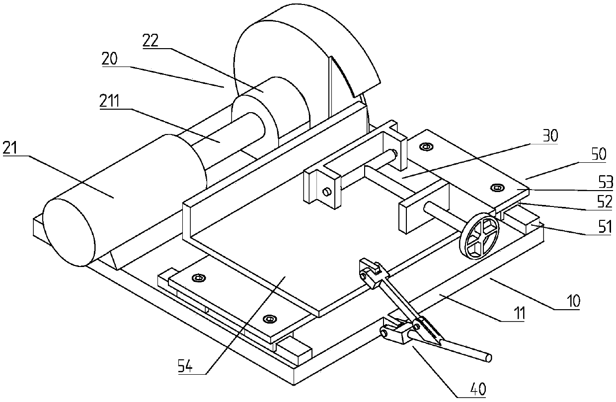
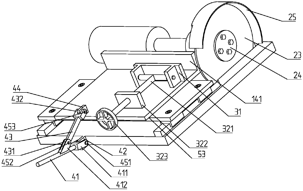
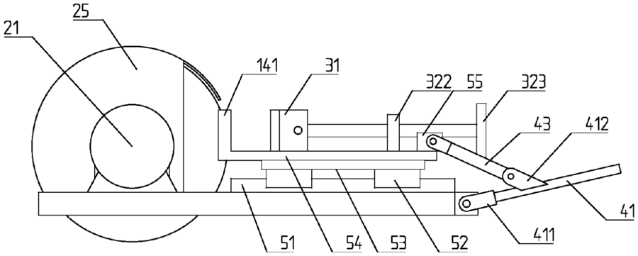
[0022] Linear guide high-efficiency cutting mechanism, including frame 10, cutting assembly 20, clamping mechanism 30, cutting assembly 20 is fixedly installed on frame 10, cutting assembly 20 includes driving motor 21, transmission shaft 211, transmission shaft support 22 and cutting blade 23. It also includes a sliding table assembly 50 and a sliding table driving assembly 40;

[0023] The slide assembly 50 includes a slide rail 51 fixed on the frame 10, a slide block 52 sliding along the slide rail 51, a connecting plate 53 fixed on the slide block 52, and a workbench 54 fixed above the connecting plate 53;

[0024] The clamping mechanism 30 is fixedly installed on the workbench 54, and the cutting piece 23 is perpendicular t...


PUM


Abstract

The invention discloses an efficient cutting mechanism for a linear guide rail. The efficient cutting mechanism comprises a rack, a cutting assembly and a clamping mechanism, and the cutting assemblycomprises a driving mechanism and a cutting piece. The efficient cutting mechanism comprises a sliding table assembly and a sliding table driving assembly, wherein the sliding table assembly comprisesa sliding rail fixed on the rack, a sliding block sliding along the sliding rail and a workbench fixed above the sliding block; the clamping mechanism is fixedly installed on the workbench, and the cutting piece is perpendicular to the workbench; the sliding table driving assembly drives the workbench to move towards the cutting edge of the cutting piece; after the cut linear guide rail is clamped by the clamping mechanism, the axis of the cut linear guide rail is perpendicular to the rotation plane of the cutting piece; and the cutting assembly is fixedly installed on the rack. As the cutting assembly is fixedly installed in the rack, the problem of cutting piece movement caused by vibration in the cutting process is solved, the cutting precision and the surface quality of an incision are improved, the cutting path is changed into a straight line, and the high-temperature problem, caused by long time contact, of the linear guide rail is greatly improved.

Description

technical field [0001] The invention belongs to the technical field of cutting devices, and in particular relates to a high-efficiency cutting mechanism of a linear guide rail. Background technique [0002] Linear guide rails, also known as line rails, slide rails, linear guide rails, and linear slide rails, are used in linear reciprocating motion applications, and can bear a certain torque, and can achieve high-precision linear motion under high load conditions. [0003] In the process of linear guide rail processing, it is often necessary to cut to a fixed length according to the designed length; the existing technology uses a traditional cutting machine for cutting, and the cutting piece of the cutting machine rotates at high speed to cut the linear guide rail, and the worker clamps the linear guide rail, and then Manually pull the drive motor and the cutting piece moves around its fixed shaft to cut, which makes the moving track of the cutting piece arc-shaped, and the a...

Claims


Application Information

Patent Timeline
Patent Type & Authority Applications(China)
IPC IPC(8): B23D19/00
Inventor 陈君
Owner 浙江鹏银科技发展有限公司
Why Eureka
Try Eureka